
Design Final Major Project (DM3103)
Roman Fort Diorama
Project Synopsis
The final major project will aim to bring Roman history to life through a Diorama, set within a Roman fort. The project will consist of both world-building and 3d modelling. Throughout my time at University, I have typically left my 3d assets with substance and never brought them into the engine. This is why I have decided to create Diorama. My hope for this project is to expand my current skill set in modelling while also gaining fresh approaches to game engine development. The project will consist of the following tasks: sketching and blockouts, modelling development, textured final renders and finally world building. The end product will consist of high-resolution screenshots that offer different perspectives through the models and the environment.
I will create 4 models for this project, one hero asset and three secondary assets that will act as supporting models to add some depth to the scene. The hero asset will be the Roman fort itself, and the secondary assets will be a farmhouse and stables. I will be downloading other assets like foliage, and they will be referenced and credited. All references will be added at the end.
The 4 models I will be modelling and developing are as follows:
Hero Asset (Roman Fortress)
Secondary asset 01 (Farmhouse)
Secondary asset 02 (Stables)
Secondary asset 03 (Barracks)
Time Management
My time management and project outline can be found via my Trello board link (Appendix 1) or within my PDF export (Appendix 2). The Trello board has two tabs, the first one containing a red line outlining the tasks and challenges that I expect to overcome and work with. The tab below, containing a green line, discusses the process and how I overcame each task, reflecting on expected and fresh challenges. The PDF export is a direct copy of my time management process from Trello. This was made in case there are issues with Trello link.
Digital Sketch (Hero Asset)
The first task was to begin designing my early sketches and outlining my art style. The first task was to choose a reference image that I felt would represent my vision for the project. The reason I opted for this design is simply that it embodies a Roman-style structure, and as a fort, it feels and looks different to a regular medieval fort that is more common in history, and this project would be very different to past historical structures that I have made.
I began with a basic outline of the structure. This was quite a challenge due to the amount of very solid straight lines, and using the mouse became a problem. I quickly found that holding shift while sketching helped keep everything organised and clean.
The annotations I have created outline my design and technical decisions when it comes to my modelling and texturing. The fort path will be developed with the game engine, while the rest of the annotations will be a part of my modelling workflow.
The Roman fort I have chosen also represents an era of military dominance and colonisation, reflecting a position of power in society. This strongly aligns with SDG 10, as the fort has a higher status and access to key resources and protection, due to its role of advancing the interests of the empire. In a modern context, this could correlate with modern governments choosing to invest heavily in military installations to advance foreign policy, while risking causing welfare and social care instability between the state and its citizens.
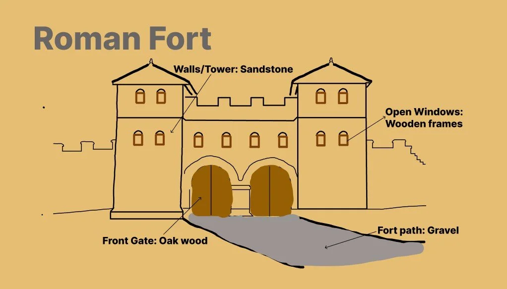
Figure 1
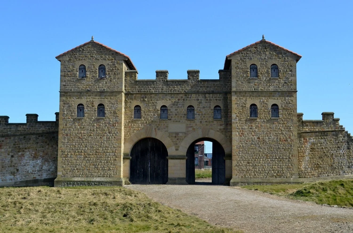
Figure 1.1: Roman forts in Britannia (HeritageDaily, 2018).
Secondary Assets 02 & 3 (Roman house and Stables)
While developing the sketch for the stables, I realised that the model would be quite simple and lacked visual depth. I decided to implement significant changes that still included elements of the original design while introducing new creative decisions.
I had the same view on the main farmhouse; the main change here was to design the model with textures that work well with the Roman theme. Rather than the wooden design, I decided to make the model with Roman materials and techniques, which would greatly improve authenticity and realism.
I believe the changes made here will make the asset feel more of my own design and will be built into the rest of the scene. The wooden panels and the stone base e will remain; however I do believe that it will enhance the project’s credibility for creating a historical scene.
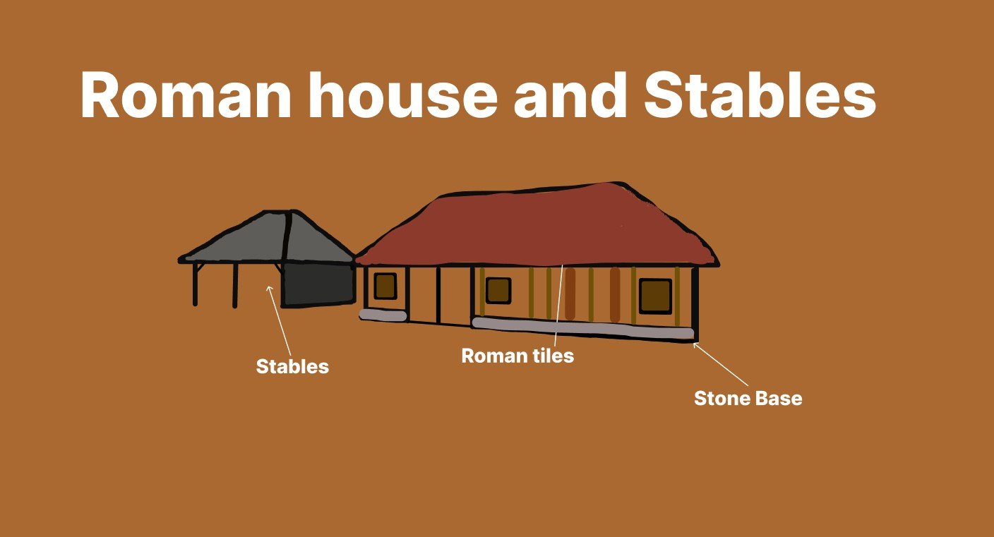
Figure 1.2
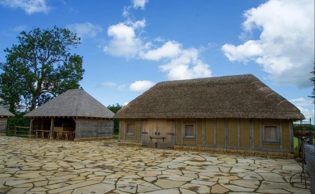
Figure 1.3: Villa Ventorum at The Newt exterior (Exploring Building History, 2022).
Secondary asset 04 (Roman Barracks)
The final model design required was the Roman barracks. This is a key asset for a castle or fort, and I found a reference image that suited my design.
The key skill I anticipate is creating the tiles; this is a design choice I have never made before, and I feel it will be a good challenge to work towards. This will add realistic historical detail to the model and will blend in with the other assets, like the farmhouse.
To understand historical realism, History Rome (2026) states that ‘the barracks were arranged in uniform rows along the interior streets, providing organised living quarters for the soldiers’. This layout shows how the Romans valued structure and hierarchy, which can be linked to Sustainable Development Goal 10 (SDG 10) through the idea of inequality. This specific source supports my approach to designing an organised and realistic Roman barracks, therefore developing a more authentic scene.
Figure 1.4
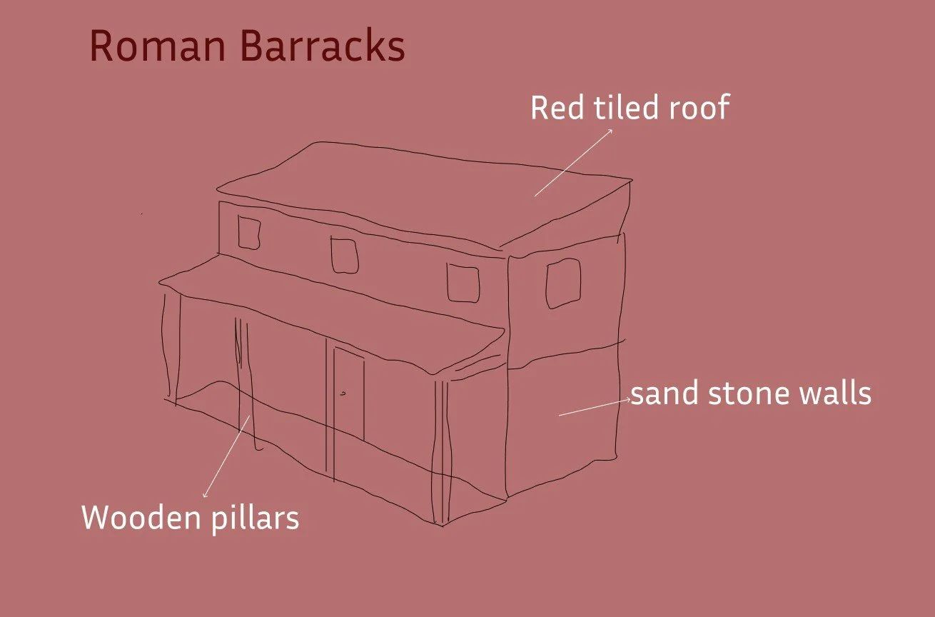
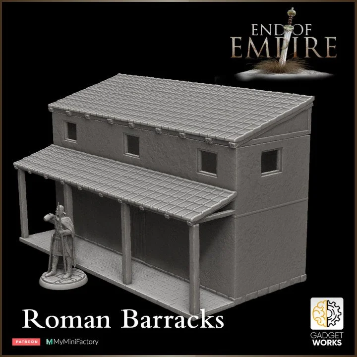
Figure 1.5: Roman barracks reconstruction (MyMiniFactory, 2022).
Top Down Map (Blockout)
Within (Figure 2.6), I have created a top-down map that demonstrates my vision and direction for the project. To develop this sketch, I decided to use Figma, which was due to its simple user interface.
The process began by adding cubes representing different assets and terrains. My vision for this project was to create a mountain range that surrounded the Roman fort and the other secondary assets. This would allow me to create vistas that offer fresh perspectives looking down into the scene, which will be crucial for my high-resolution screenshots.
The Archaeologist (2024) explains that the Roman roads were often constructed in straight lines wherever possible, allowing for more efficient movement of troops, communication and trade across long distances. This source was important for understanding my approach to creating a suitable pathway that leads through the mountain range towards the fort.
The foliage will likely be a mix of trees and grass that I aim to place alongside the Roman road, which leads around the fort and within the range. The other area was to create a dense forest at the edge of the scene, which helps to contain the scene and creates a more congested environment.
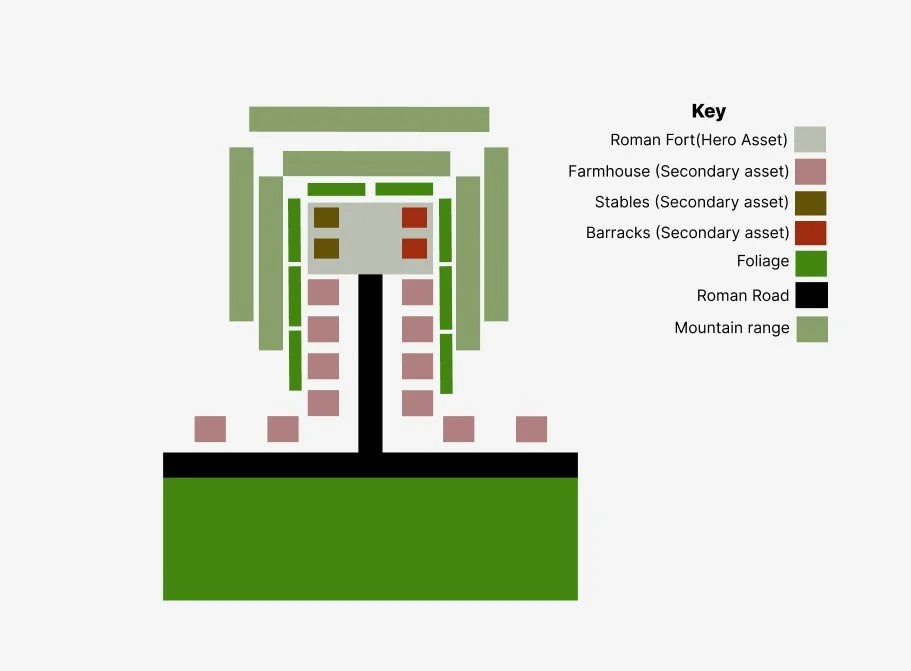
Figure 1.6
Every event we host is designed with intention, from the atmosphere we create to the way each session flows.
Roman Towers Stage 01
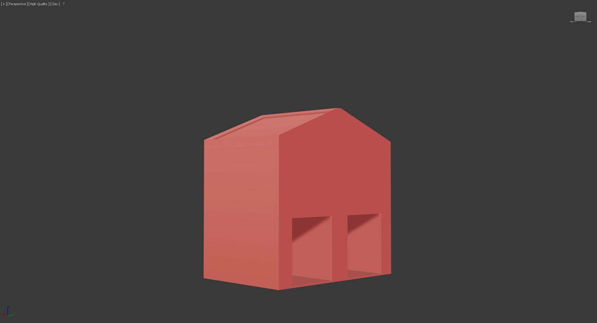
Figure 1.7
The first step in creating the towers was to focus on the scale and measurements. This will allow me to focus on consistency and reusability, which are key concepts of the project that match the walls and towers, so the assets look and feel equal. The main task here was to build the tower’s roof. I added in 1 swift loop to create a suitable edge, and then extruded the edge upwards. The angled edges were created using the bevelled tool. This creates the inverted edges within the inside of the asset for the roof.
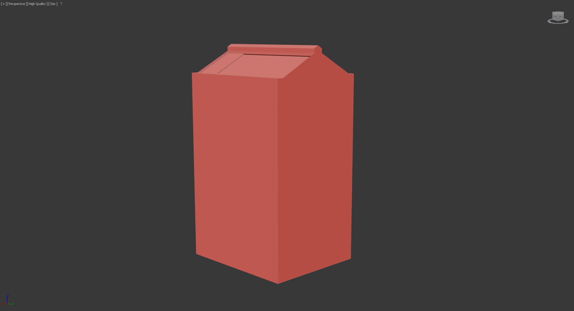
Figure 1.9
Figure 1.8
The only issue and error I encountered while modelling the walls and towers for the castle, the process was simply creating a cube that fitted cleanly between the towers and main gate. I repeated the process for creating the walls; however, once I cloned them, I made the mistake of cloning them as instances and not as copies. This caused the asset to multiply during the attachment process, therefore creating overlapping assets and poor typology. This did happen to the windows, as I did not realise at the time until I cloned each of the assets.
Challenges and errors (Problem)
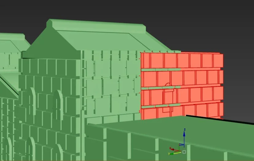
Figure 2.1
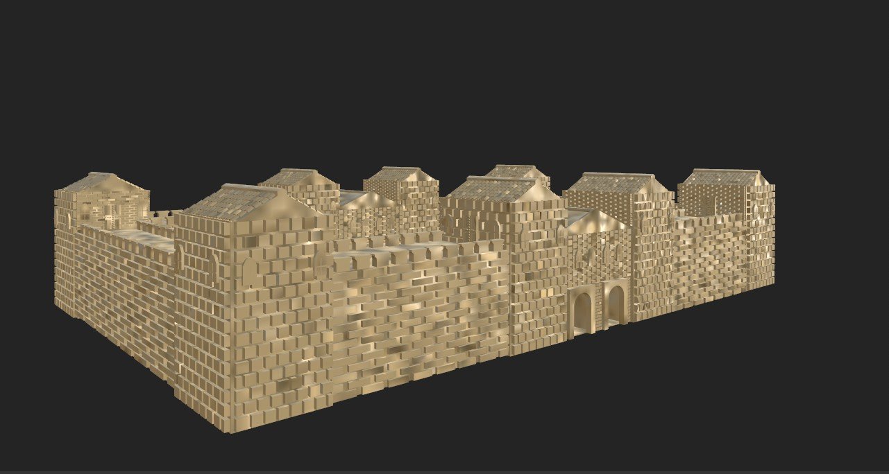
Figure 2.2
Windows (Before refinements)
Once the cuts were made, I could begin adding key detail points. The first task involved using a new skill to create a brick asset that could sit on the face to add some visual detail. The process to make the bricks was to select polygonal modelling, then I chose the brick pattern. Once inserted, I could chamfer the edges and extrude the cubes out, which created the brick detail. The other method, which I typically have used, was to add swift loops across the face and extrude each of the created polys. The challenges with using this method are that you never see clear gaps between the bricks. I believe the polygonal modelling method works for this specific task. The archway and windows were added after the bricks had been created in order to manage typology and to avoid overlapping layers.
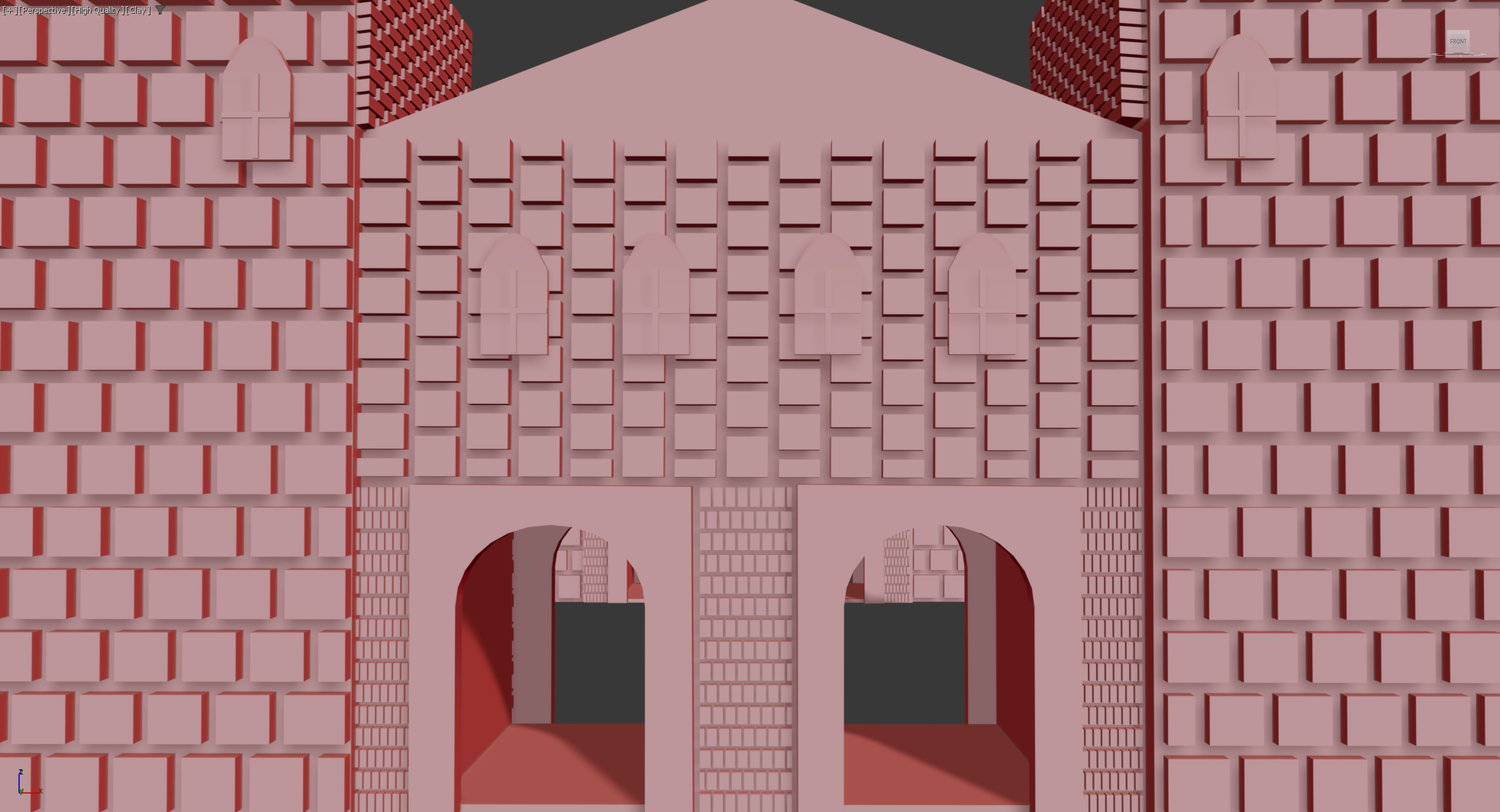
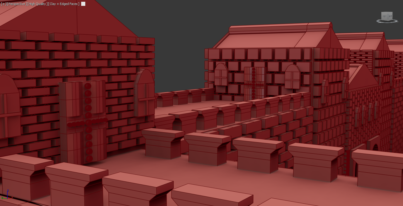
Roman Towers Stage 02
The process for adding detail involved adding the arched windows and the bricks to the towers, the only difference being the addition of new polygonal modelling. The bricks were made again to fit the specific shapes and dimensions, which, compared to the walls and main gate was very different. Once one of the towers was completed, I could clone it and quickly place it in the specific locations.
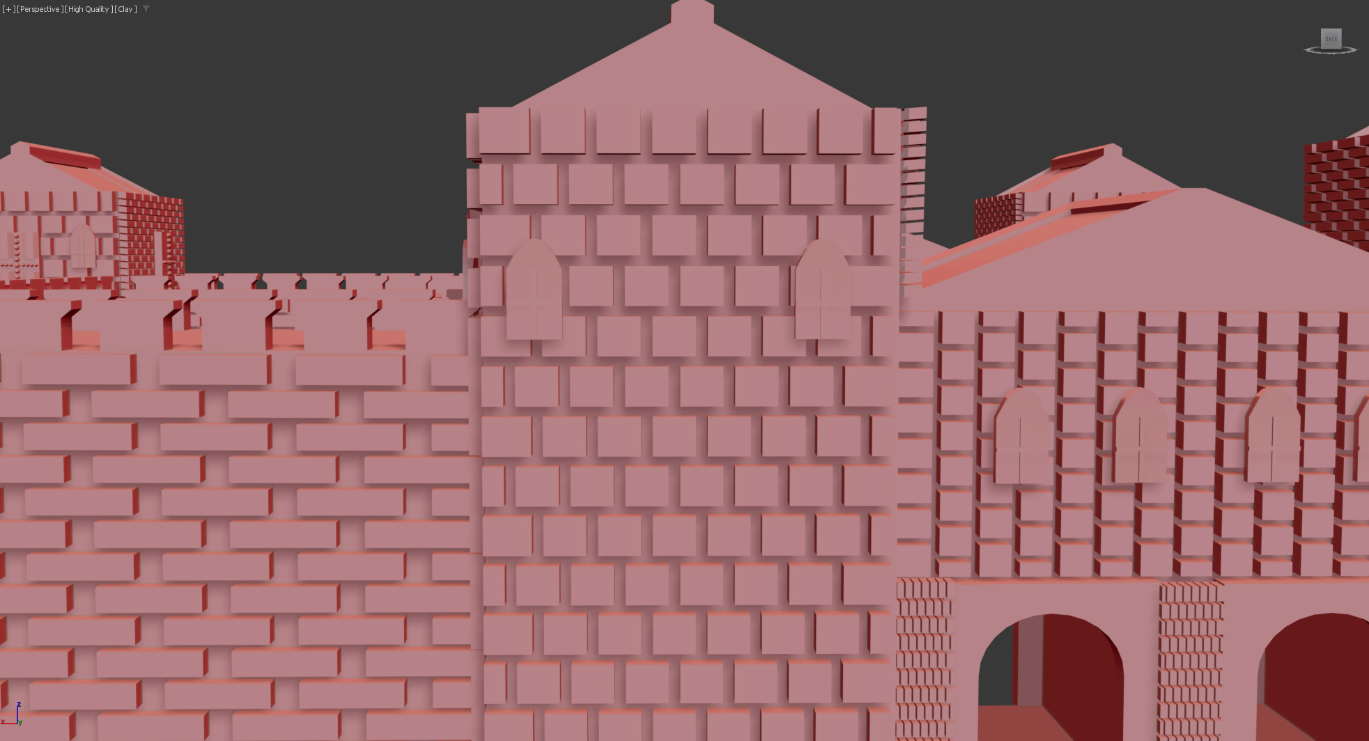
Figure 2
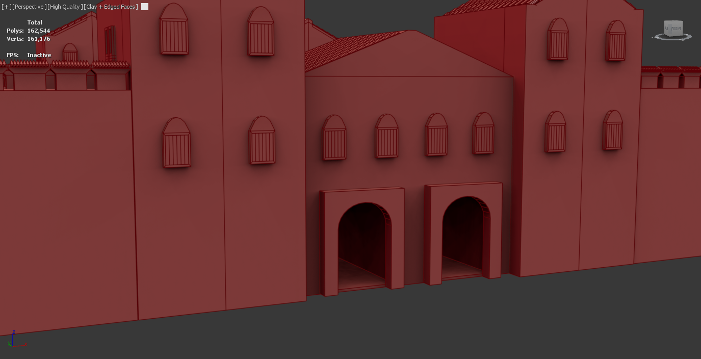
Texture test
To understand this challenge further, I decided to conduct a texture test. I imported the model into substance and the results were that some parts of the model textured fine and some parts did not. The polygon selection tool was not accurately applying textures to assets like windows and doors, which resulted in the model being of a lower quality and lacking key details.
To further this, I tested the model into ue5, and the textures did not reflect the export from Substance. This result convinced me that the bricks were causing more issues than they were worth, and I decided to delete them and focus on improving other key assets to ensure the final model looked as good as it could. Figure (2.2) shows the substance texture, and Figure (2.3) shows the UE5 export.
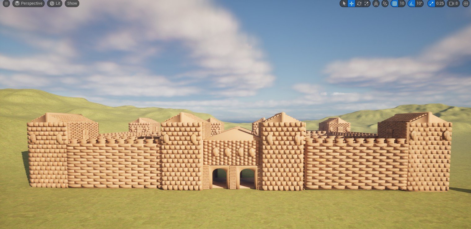
Figure 2.3
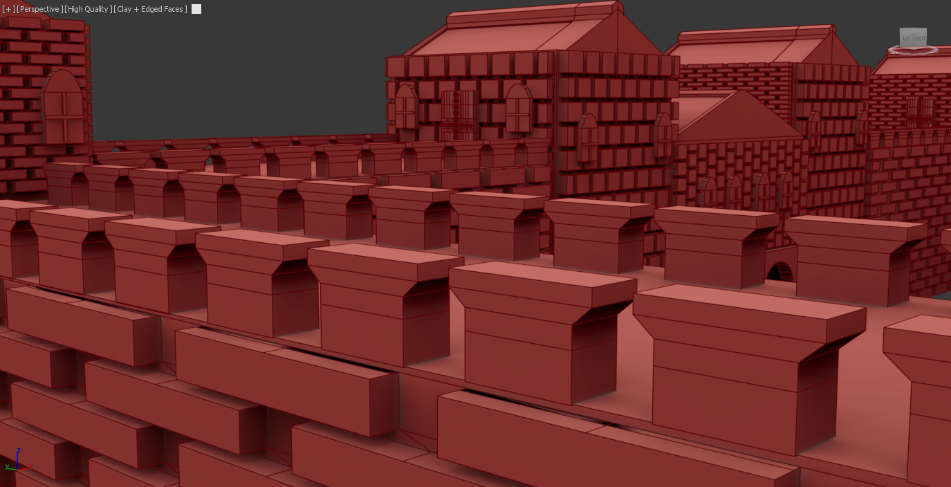
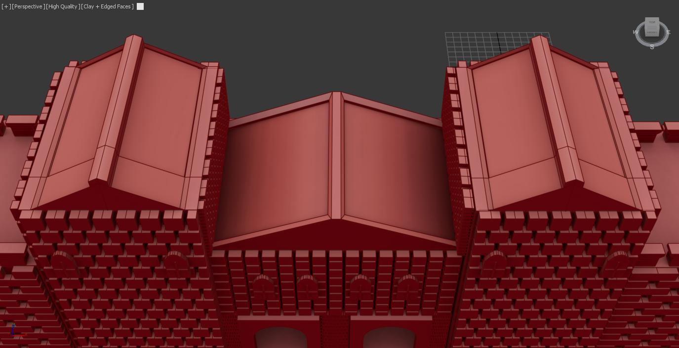
Structural Refinements
While I did decide to remove the bricks, I did want to make some key refinements to minor assets like windows, doors and the barriers and finally tiles . The changes I made to the windows were to add wooden planks to the windows, which added a more realistic appearance. The windows were simply flat surfaces, and this lack of detail would not represent the vision I had for the project. The doors needed improvement as they had uneven surfaces and visual detail that I do not believe was a suitable design. Both the windows and doors did have problems with the polygonal selection, so I knew this was something that needed to be fixed. The wall barricades contain gaps between each of the assets, which was a mistake I made while using the array tool. The changes for this are to add spikes, which I feel would make the fort look more secure and more historically realistic. The tiles were not originally added, mainly due to the already high poly count due to the bricks. Since their removal, I decided to add them to the model. The tiles were created by bringing in a cylinder and cutting it in half to create the shape. I then used the shell modifier to create the thickness. This was then placed on the roof, where I could duplicate using the array tool along the roofs. To highlight my commitment to SDG 10, the refinements demonstrate how the Roman hierarchy and its culture operate to support critical military buildings at high costs. The increased level of detail regarding defensive aspects like the spikes highlights the level of wealth and material distribution between government and civilian structures.
The changes for the windows are kept in (Figure 2.4) and (Figure 2.5).
The Door improvements are situated within (Figure 2.6) and (Figure 2.7)
The wall barricades improvements are within (Figure 2.8) and (Figure 2.9).
The creation of the tiles are located within (Figure 3) and (Figure 3.1)
Figure 3
Windows (After refinements)
Figure 2.5
Doors (After refinements)
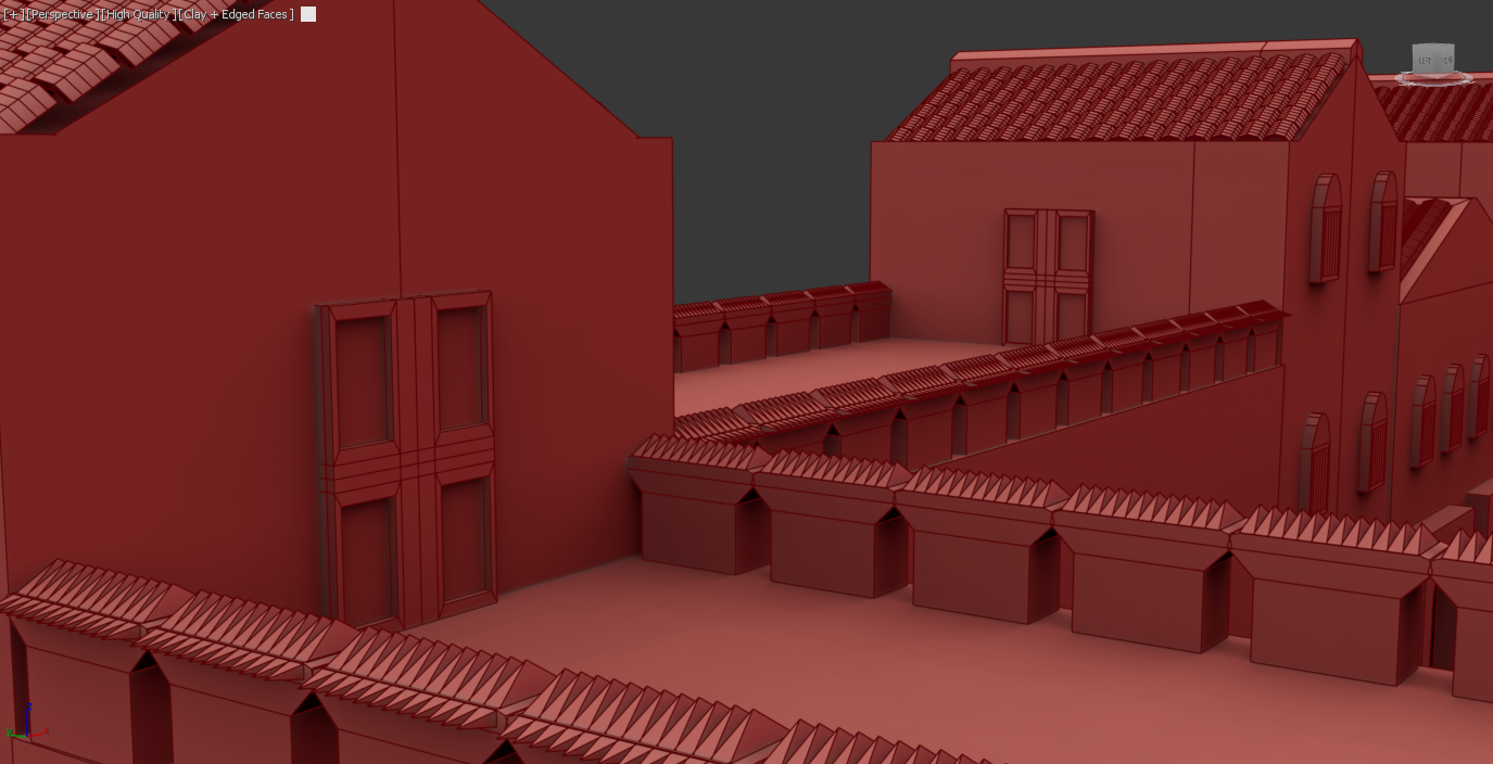
Figure 2.7
Wall barricades (After refinements)
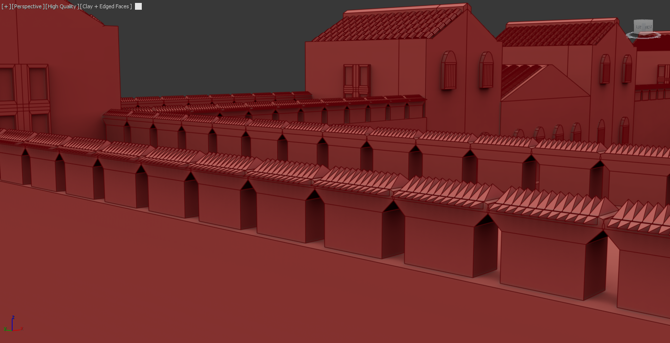
Figure 2.9
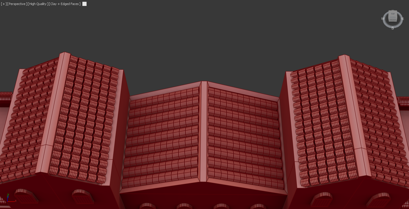
Tiled Roof (After refinements)
Figure 3.1
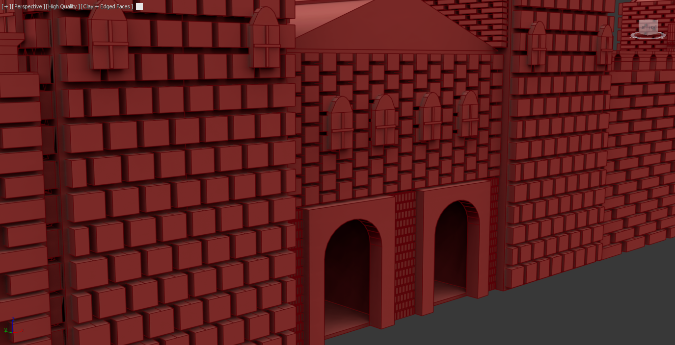
Figure 2.4
Doors (Before Refinements)
Figure 2.6
Wall barricades (Before refinements)
Figure 2.8
Tiled Roof (Before refinements)
Roman Fort (Modelling Stage 01)
Roman gate (Stage 01)
The first stage of developing the main gates was to add a cube and begin by scaling it to a realistic height and width. To make it accurate and realistic, I brought in a cube to act as the tower, which allowed me to make a judgment of the size of the assets. The second objective was to create cuts into the wall that could be suitable for archway structures. One issue I encountered was that the pro-Boolean tool created an inaccurate cut using the archway, which led me to a basic insert using a cube. This method created equal cuts, and while it was not the specific arch insert, I was still able to utilise a archway shape to create the detailed viewpoint through the fort.
Roman Gate (Stage 02)
Roman Farmhouse (Secondary Asset 01)
House structure and tiles
The main task for the farmhouse was to import the tiles for the roof. To improve efficiency, I decided to utilise the same tile asset from the Roman fort; this decision made the model more consistent and demonstrated how I aim to create a clear connection between the other assets. The main difference between the fort, tiles, and these was a reduction in scale and positioning due to the roof’s angles, which was important for avoiding polys interacting negatively with each other. To link to SDG 10, the process of reusing specific assets encourages designers in the modern world to be more efficient and make projects more accessible to those with little experience or limited equipment. This specific process will be later repeated within the Roman barracks modelling process (Figure 5.2)
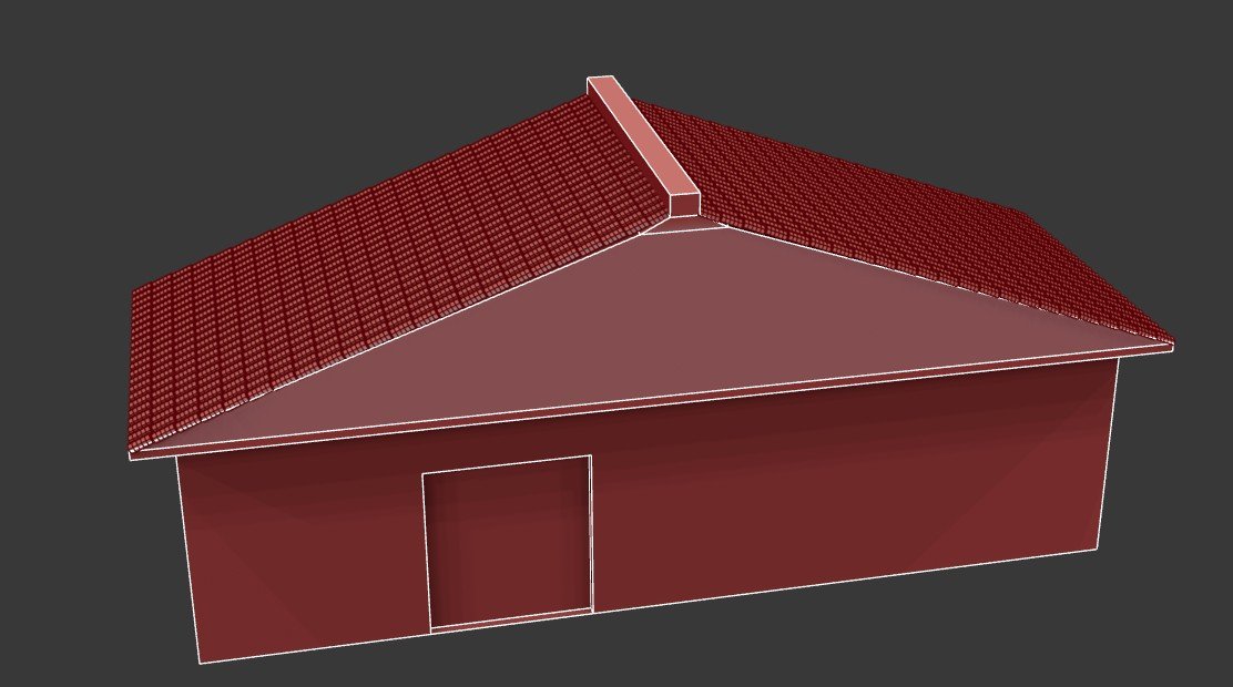
Figure 3.2
House Windows
The windows were developed by using two cubes; the design began by adding a swift loop to each of the corners. I was then able to extrude the shape inwards, which creates the gap to add the window frames. I could have undertaken this by using the original asset to create the frames, but that would have encountered issues that could cause issues with UVs. I also felt this looked much closer to the reference image meaning it was more visually appealing.
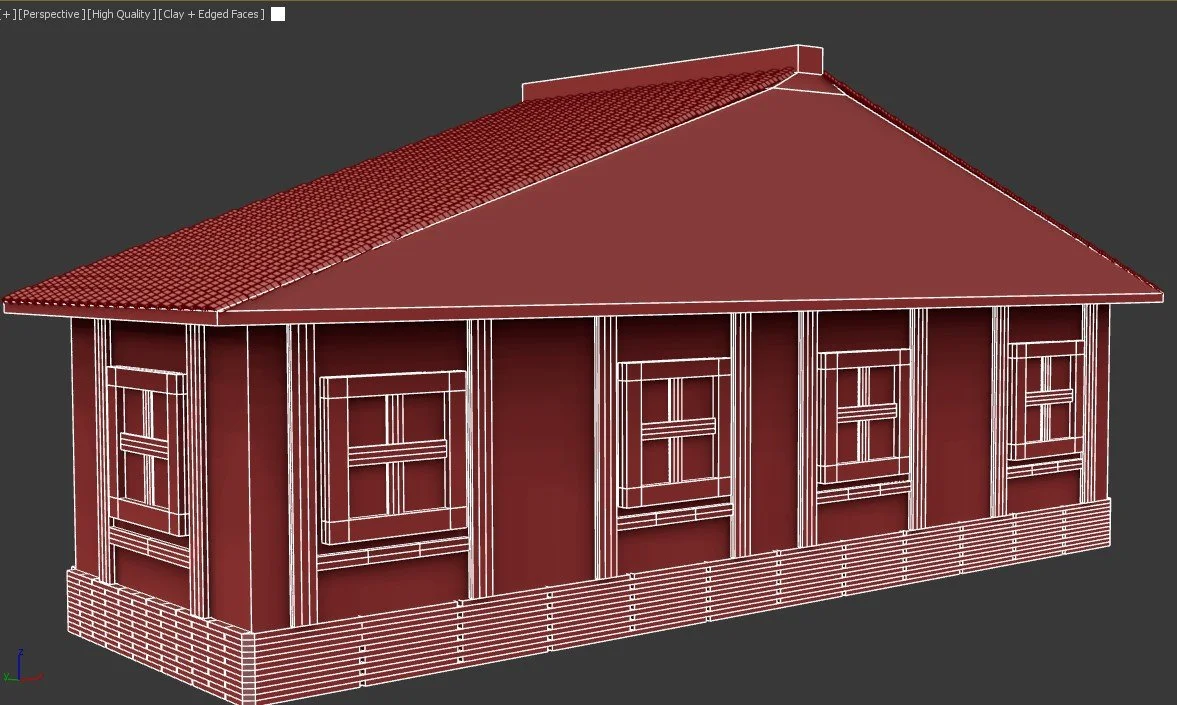
Figure 3.4
Main door and lower walls
The door was designed using a cube shape, which was then extruded to make the cut in the wall, I then cloned the asset which allowed me to begin adding the key details. The first was 4 small cubes that were attached to the cube to act as anchor between door and the hinges. The second shape was acting as the ropes, I completed this by adding a set of torus shapes, while applying the array too keep accurate spacing along the door. The lower walls followed the same workflow to add the bricks to the lower area of then model.
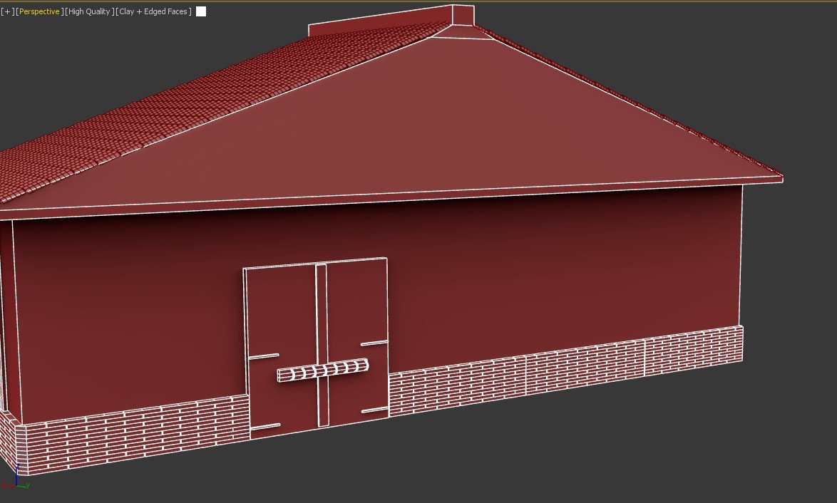
Figure 3.3
Roman stables (Secondary Asset 02)
Roof frames
The original design of the stables did not have enough visual appeal, and I decided to make some changes to the structure. The first task was to create the frames for the roof. I began by adding a cube and then creating an angled asset that would connect downwards to create a suitable frame. To avoid the asset looking consistent, I rotated the bottom faces to sit on each edge; the other reason was that the cube was not positioned properly and it made the model look uneven.
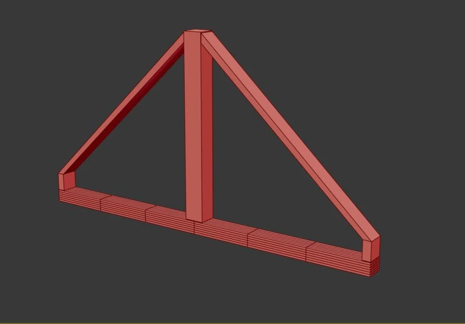
Figure 3.5
Roof completion
Once the roof planks and frames were in place, I was able to clone the wooden planks to fit each of the gaps. I angled each of the faces and fit them into place, which were accurate due to the accurate spacing using the array tool. One important factor during this process was remembering to clone as a copy and not as an instance. This was a problem I faced during the modelling process of the fort . This demonstrated a clear response to how I deal with the challenges within a modelling practice.
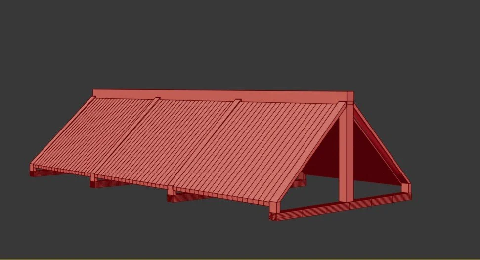
Figure 3.7
Roof wooden planks
The roof frames were cloned using the array tool. This was done to create equal spacing between the assets to ensure that the roof was equal. The design of the wooden planks was undertaken by using a cube to create the plank, which was placed at the same angle at the frame. I was then able to use the array tool to create the roof in order to maintain reusability and allow for accurate spacing. This process allowed the model to look accurate and even between both the frames and the planks.
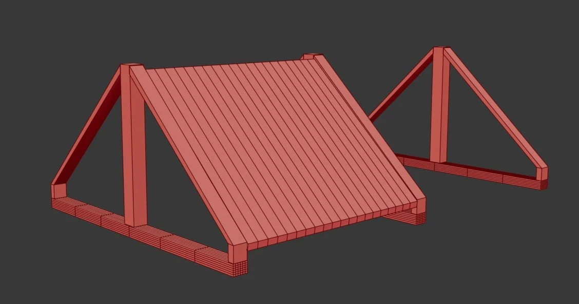
Figure 3.6
Barn development
The final task was to create the main structure. This was completed by adding 4 support beams that were placed across both sides. This process was made much easier due to the array tool, as I can cleanly align each of the main support beams. The fence was created by extruding the face of the cube inwards and then deleting each of the faces. This was done to make the model feel free and visual rather than closed in and empty of detail.
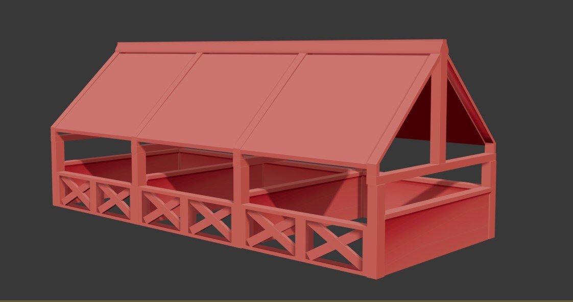
Figure 3.8
Roman Barracks (Secondary asset 3)
Barracks Structure
The Roman barracks development began by creating a slanted roof that could then create a different feeling compared to the simple flat roof design. This design choice was influenced in this way because of its visual detail and the opportunity to learn a new skill of modelling tiles, which are a crucial aspect of the reference sketches.
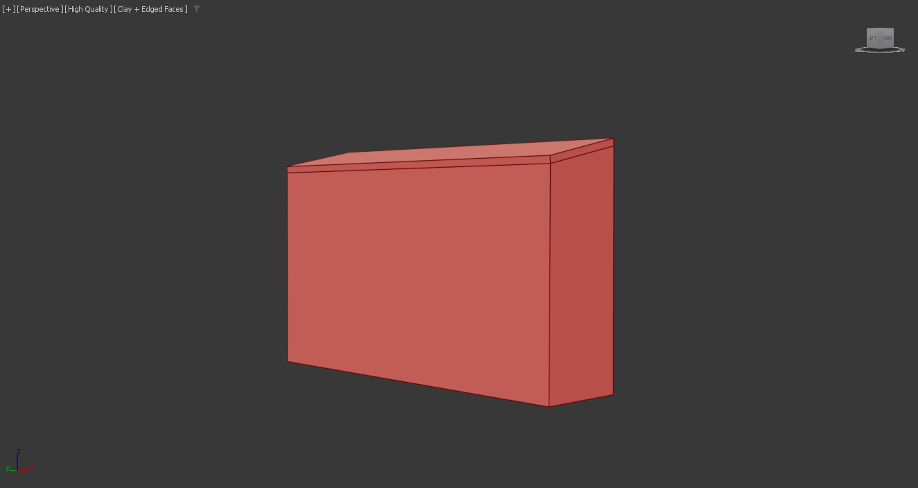
Figure 3.9
Barracks Structural details
The pillars acted to support the lower roof; this was a design that could have been completed using Roman pillars or basic cubed boxes. Although the reference image showed simpler support beams, I decided to create a more authentic asset that reflected the Roman era. The door proved to be slightly harder to do due to the angle of the reference image, which meant I could not see details like the handle as easily. To fix this, I added a torus shape to act as the handle, which felt more appropriate for an ancient/medieval rather than a modern structure.
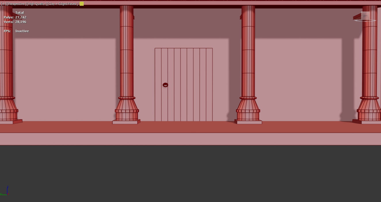
Figure 4
Roof Tiles
The process for creating the roofs was to follow the same procedure as the tiles within the Roman fort. To save time and improve efficiency, I once repeated the same process as the farmhouse by importing the tiles back into the scene. The only challenge with this was to scale and resize the asset down to fit the barracks. Once the tile was scaled and placed began to use the array tool to efficiently duplicate the asset along both sections. This process not only supported the reusability of assets while also maintaining historical realism.
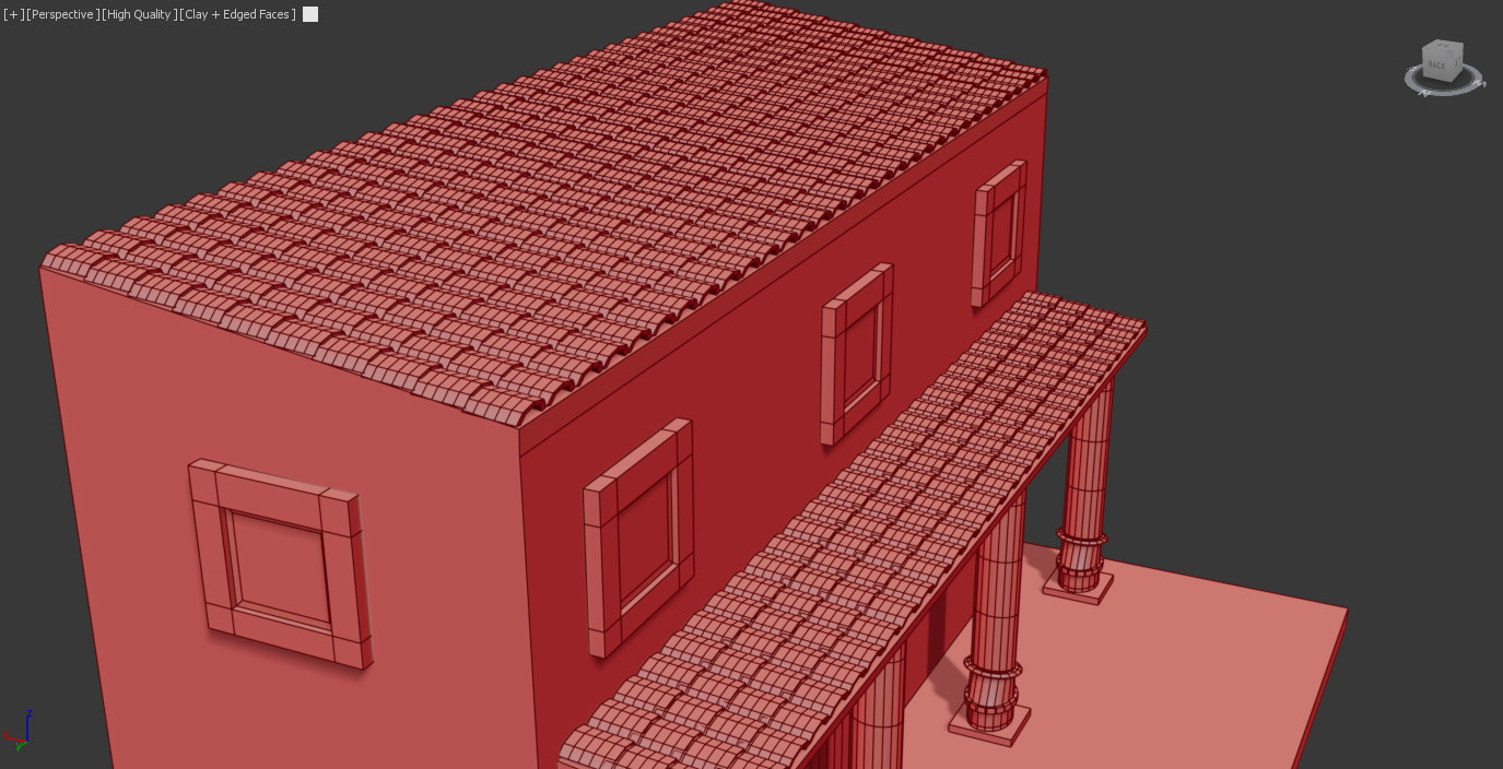
Figure 4.1
Roman Fort (Final Textured renders)
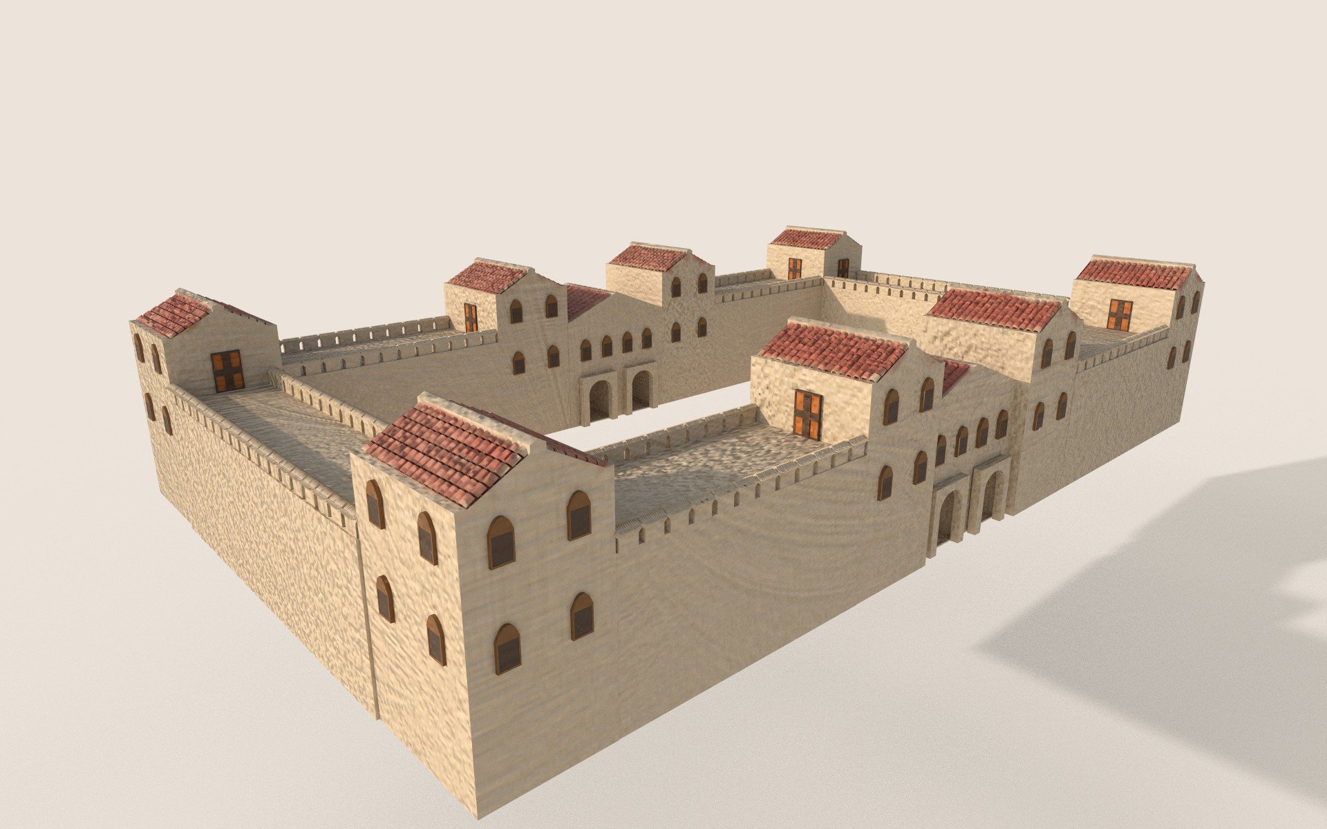
Figure 4.2
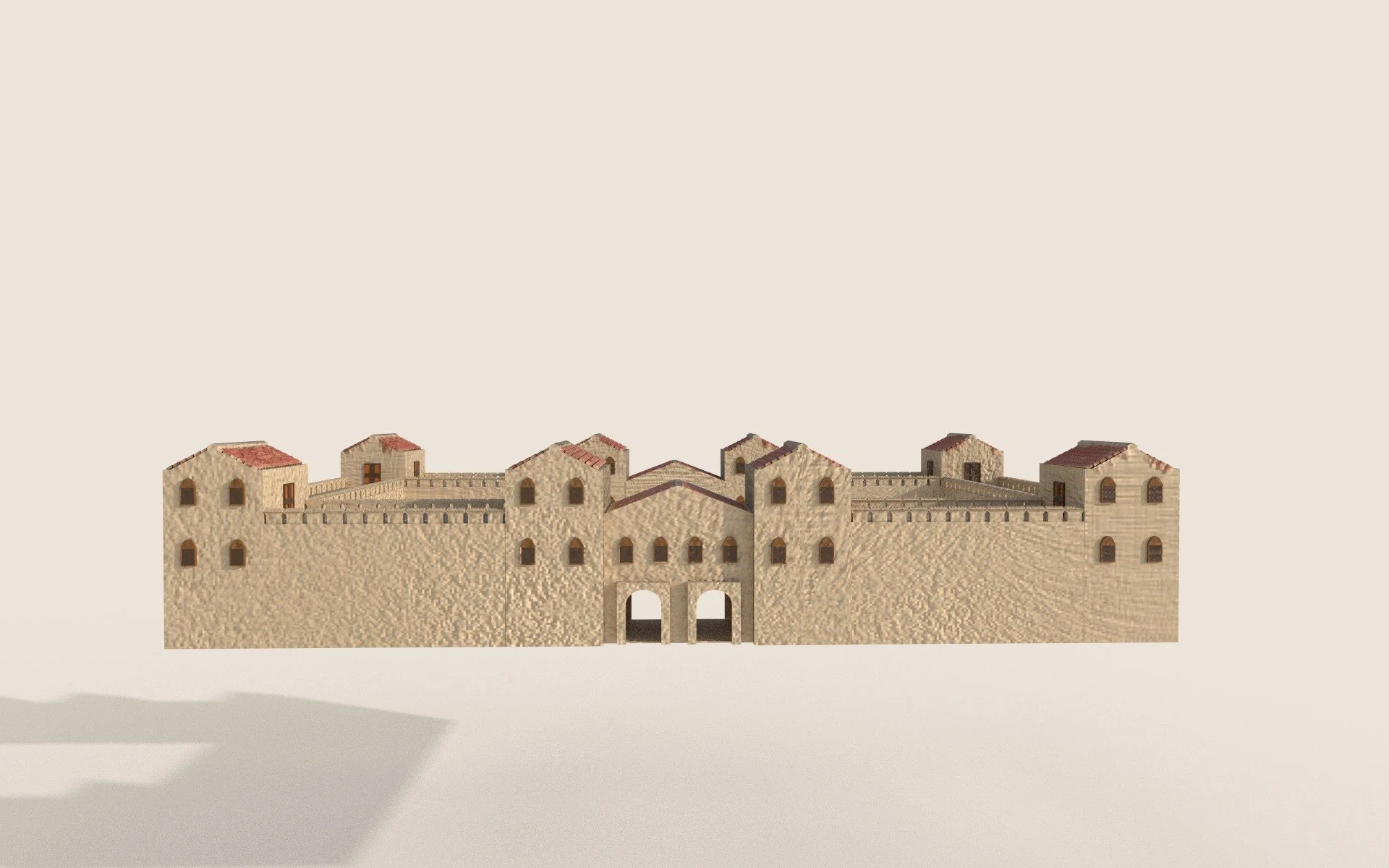
Figure 4.3
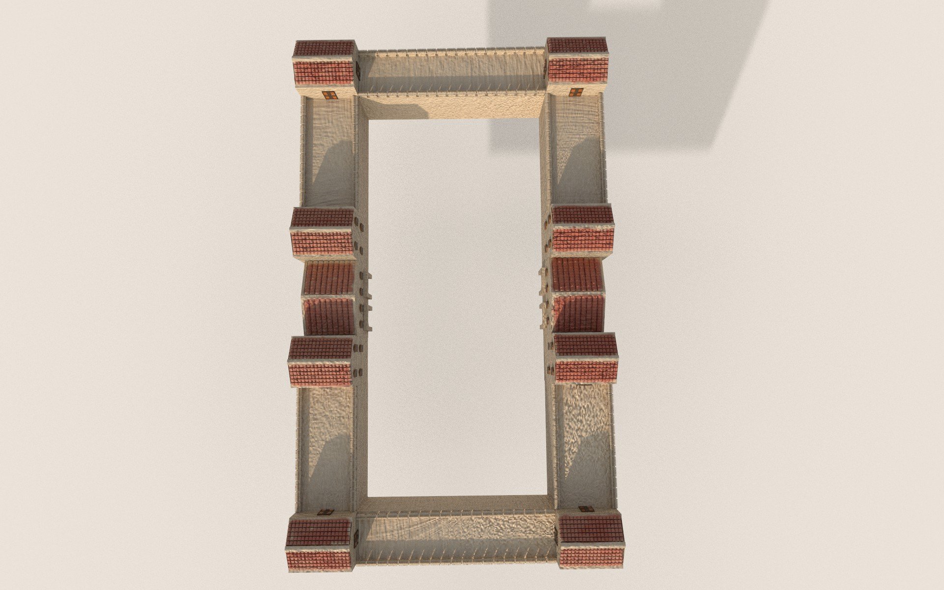
Figure 4.4
Roman Farmhouse (Final Textured Renders)
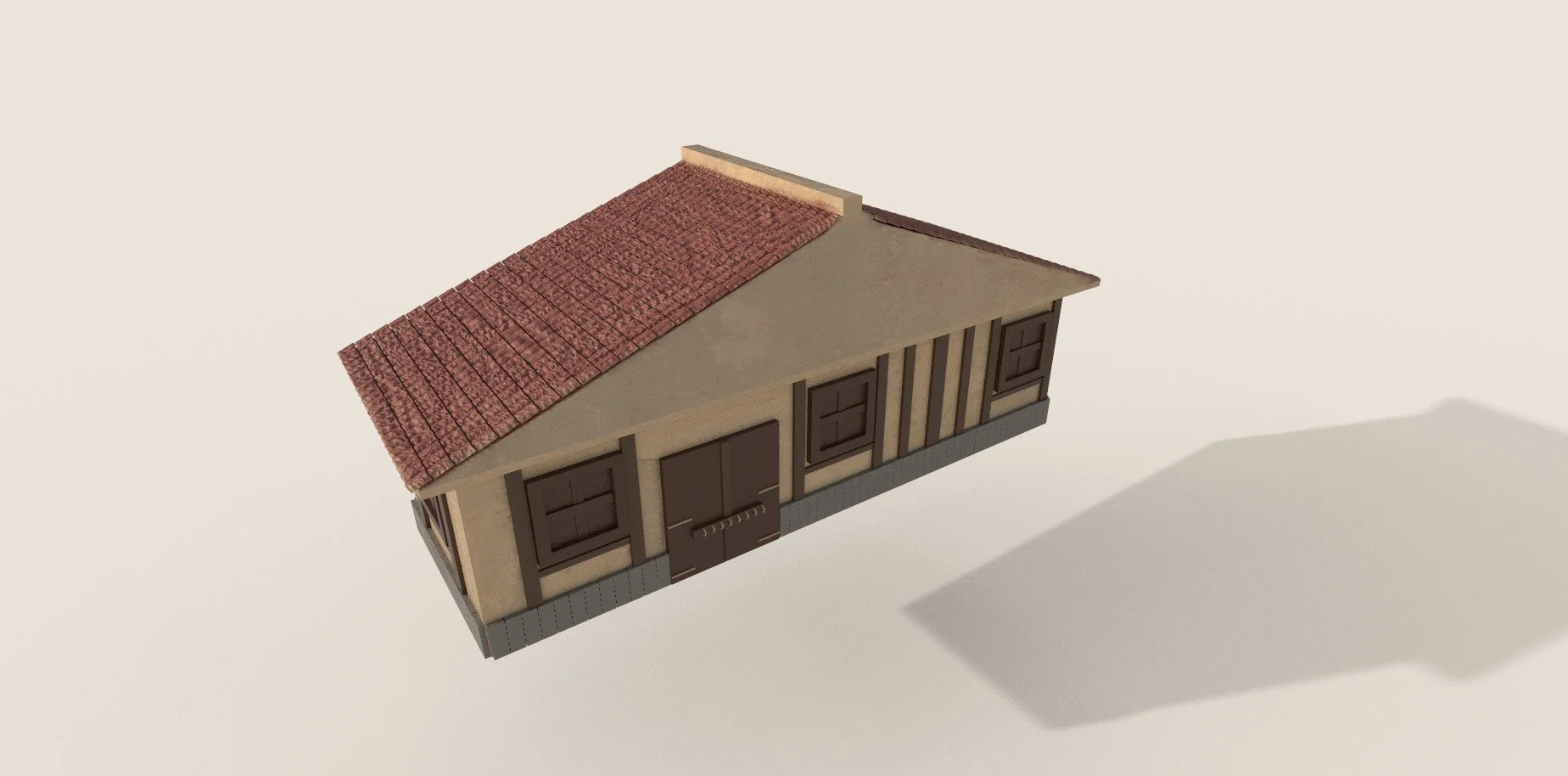
Figure 4.5
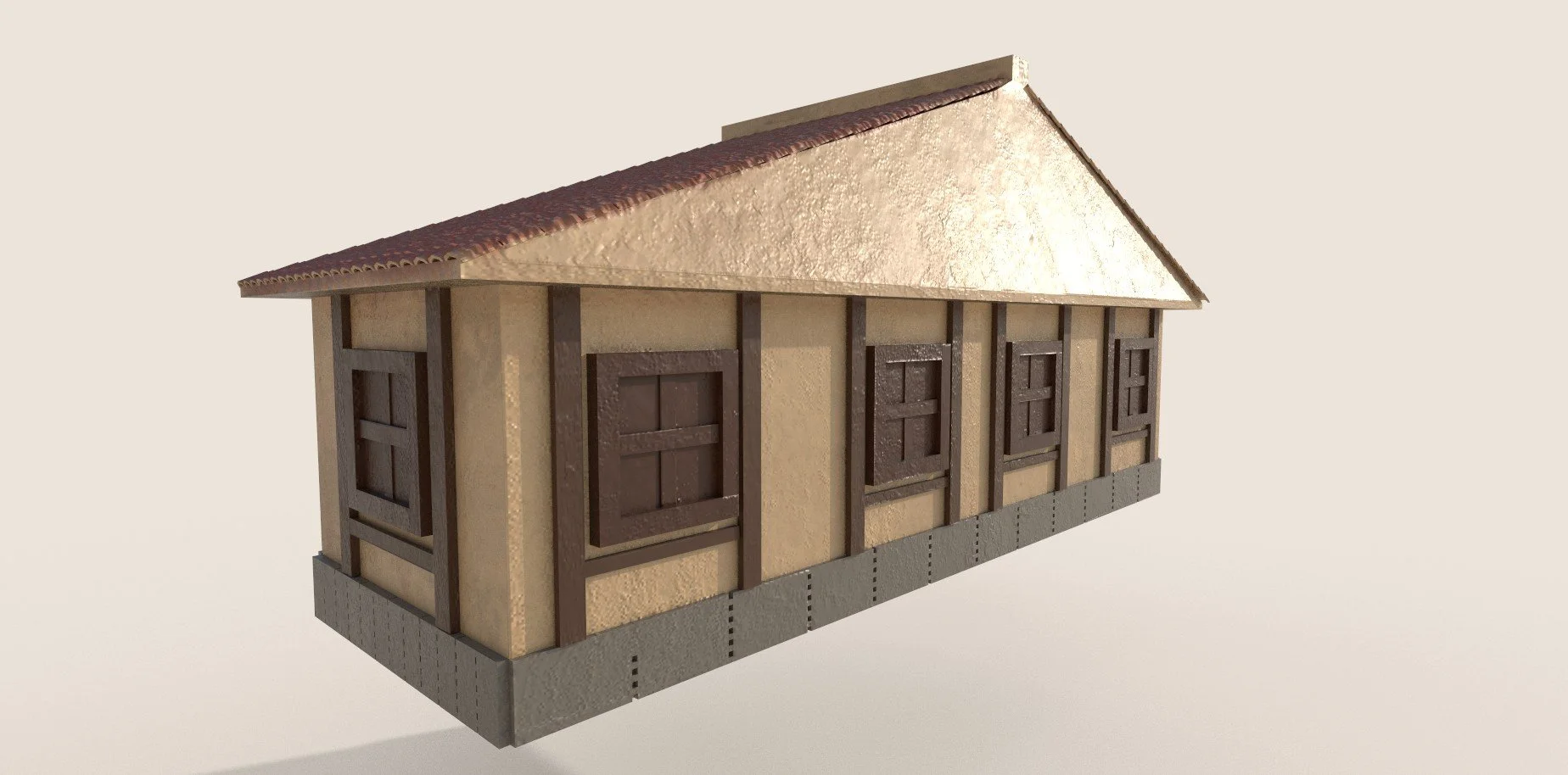
Figure 4.6
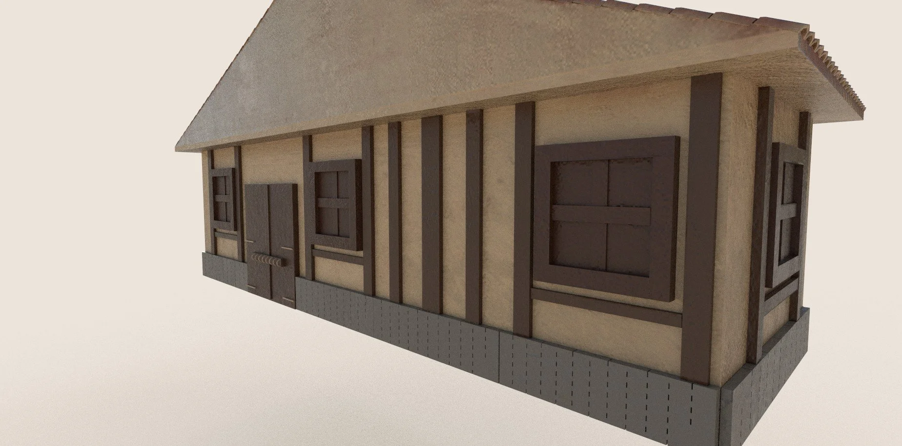
Figure 4.7
Roman Stables (Final Textured Renders)
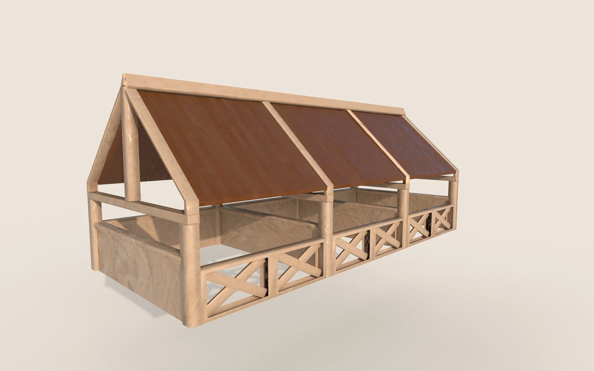
Figure 4.8
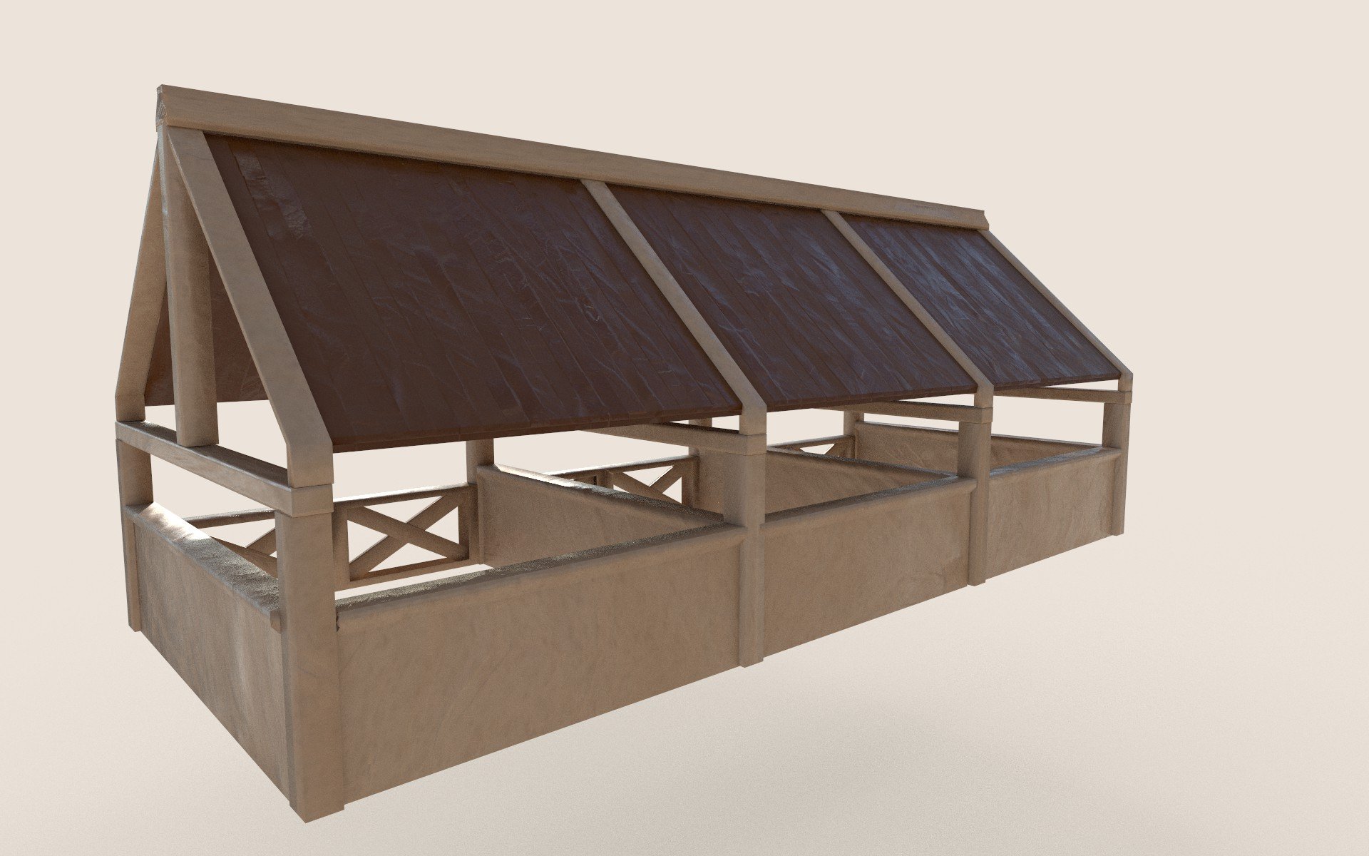
Figure 4.9
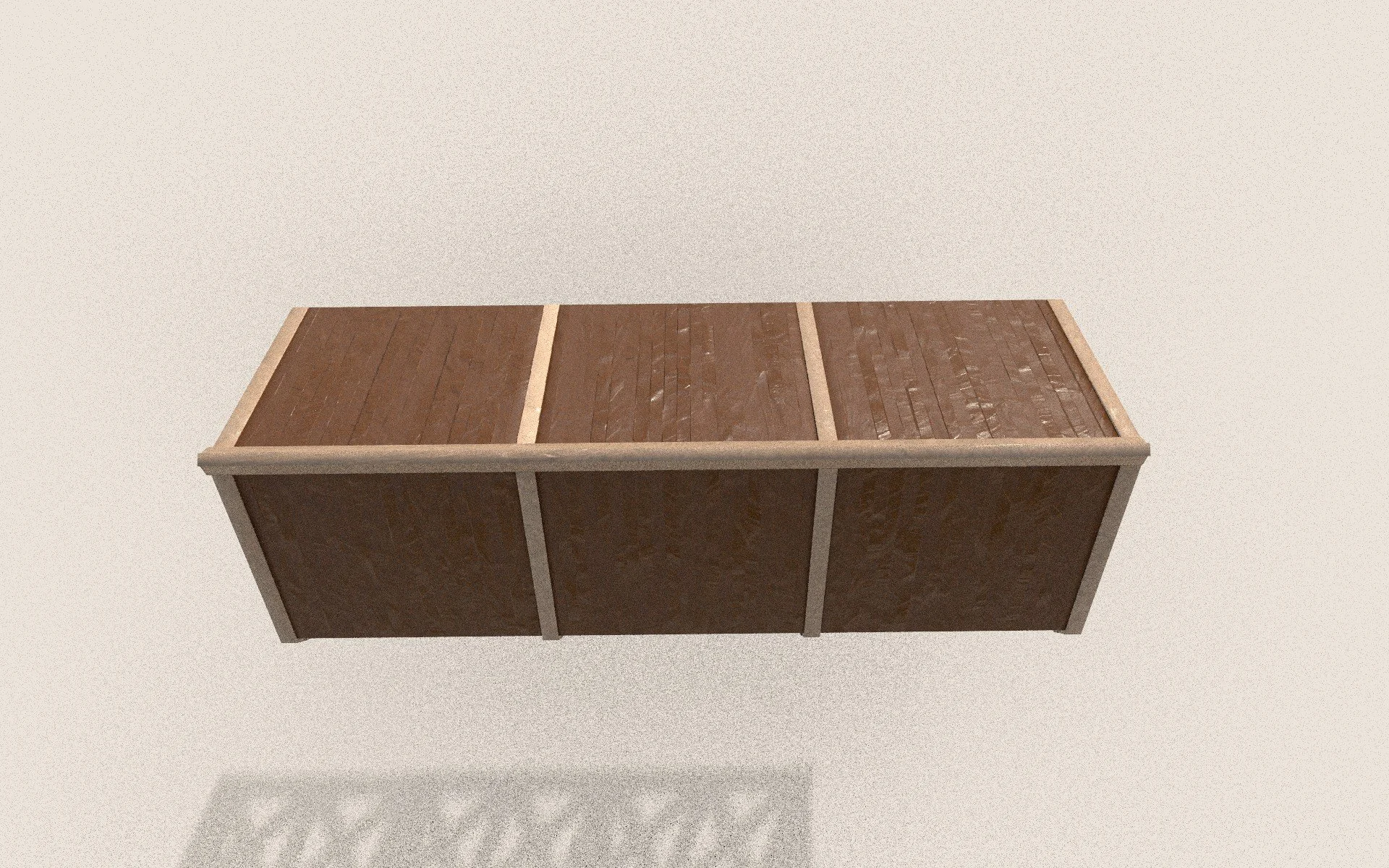
Figure 5
Roman Barracks (Final Textured Renders)
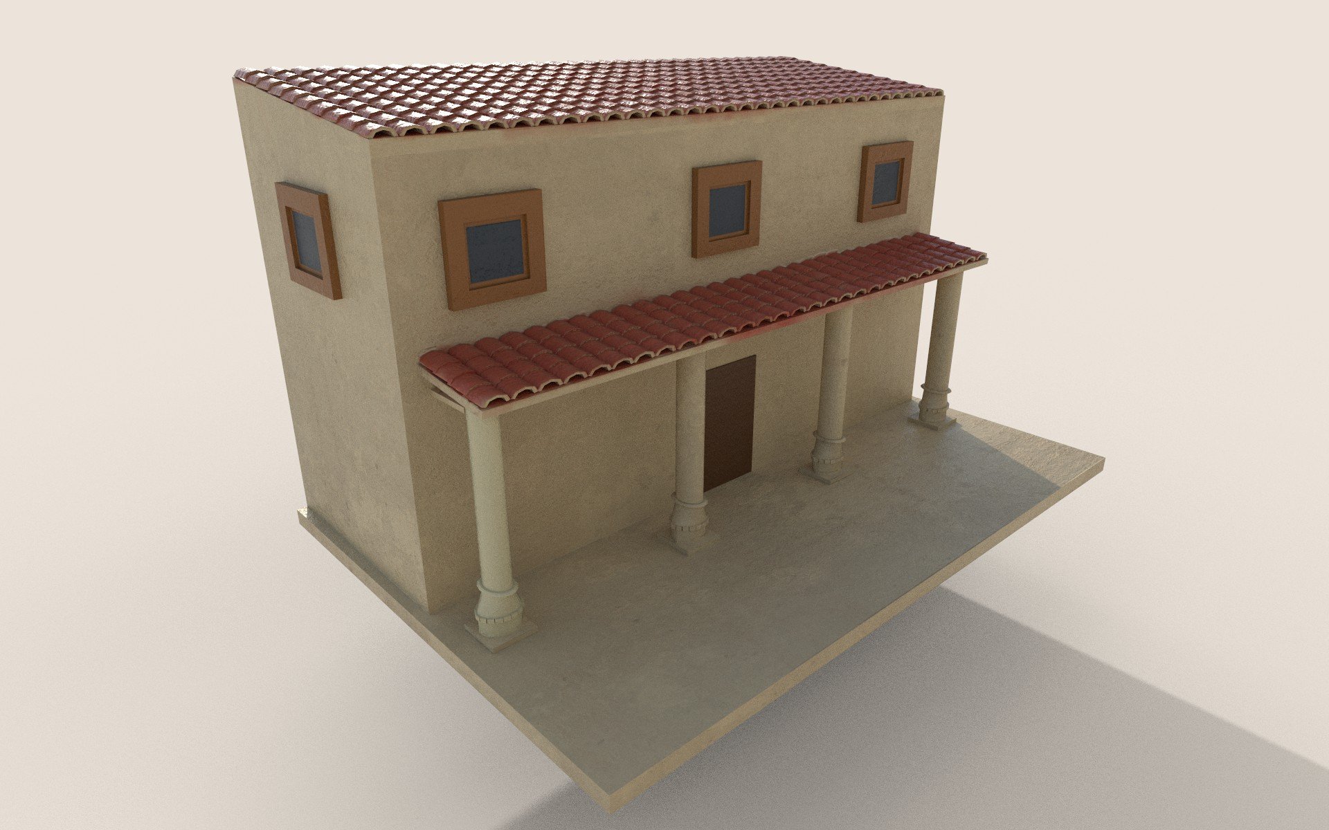
Figure 5.1
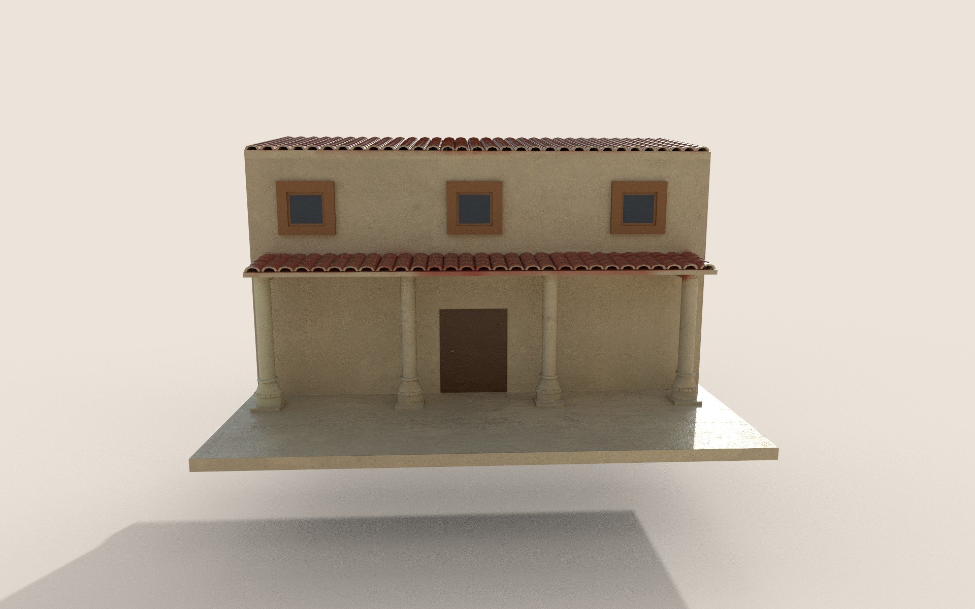
Figure 5.2
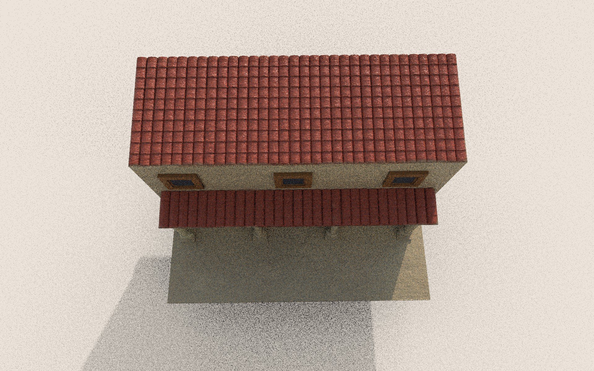
Figure 5.3
Environment Development Process
Stage 01: Downloaded Assets
The first area I will discuss is the downloaded assets. The assets I chose were to offer increased depth and realism to the world I want to create. The first asset was a forest material, which was chosen due to its contrast between dark and light colours and its connection to the grass foliage asset, which was unique in its ability to blend in with the forest asset. The 3rd asset I added was a tree asset. I had different models in mind; however, the one I looked at felt slightly too cartoonish, which would not have suited the art direction for my diorama. This encouraged me to choose the tree below, which I felt suited the project better. The final asset I downloaded is the stone pathway. While looking at Quixel mega scans, I found a Japanese-style stone pathway that, while not Roman in origin, did resemble the bricked Roman road, fitting both my scene and artistic vision.
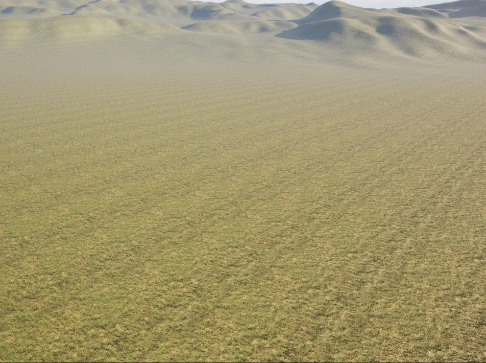
Figure 5.4: Forest floor asset (Quixel Megascans, 2024).
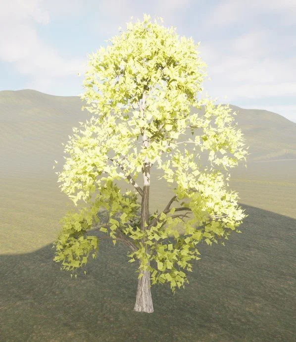
Figure 5.6: High poly tree model (Next Spring, 2025).
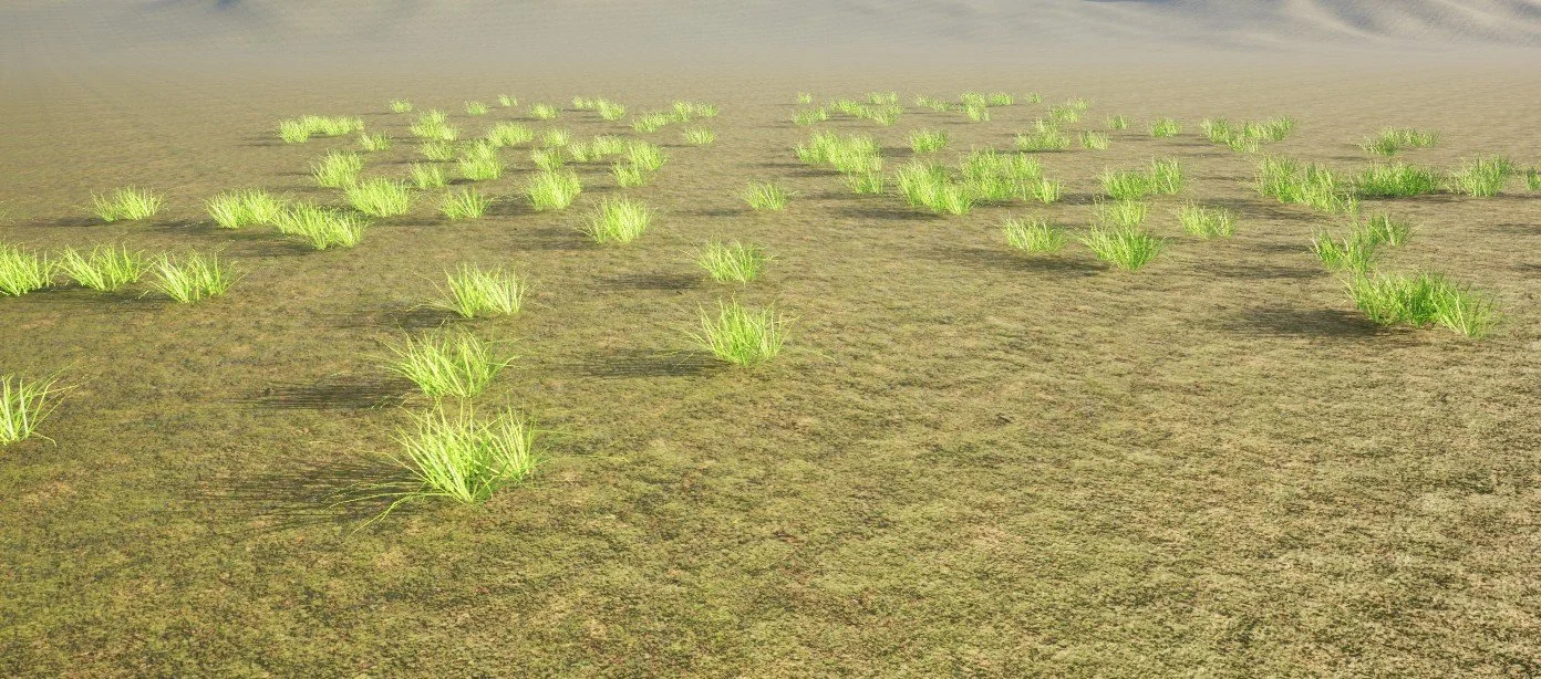
Figure 5.5: Grass 3D model (Ogussstavo, 2025).
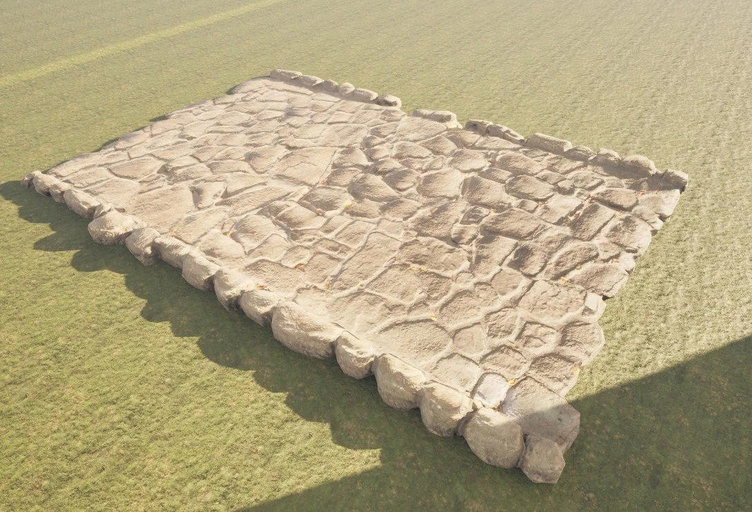
Figure 5.7: Japanese park stone floor (Quixel Megascans, 2024).
Environment Development Process
Stage 02: Landscape development
The vision for the diorama was to create a set of the mountains and hills that surround the Roman settlement, displaying depth and congestion.
The first step was to add the landscape material and begin attaching the textures within the material graph. Since this texture was downloaded from the UE5 marketplace, I understood that I only needed 4 specific textures to create the material: Base material, Roughness, AO (Ambient Occlusion) and finally Normal maps. These were combined within the material graph to produce surface detail with realistic lighting and depth across the landscape.
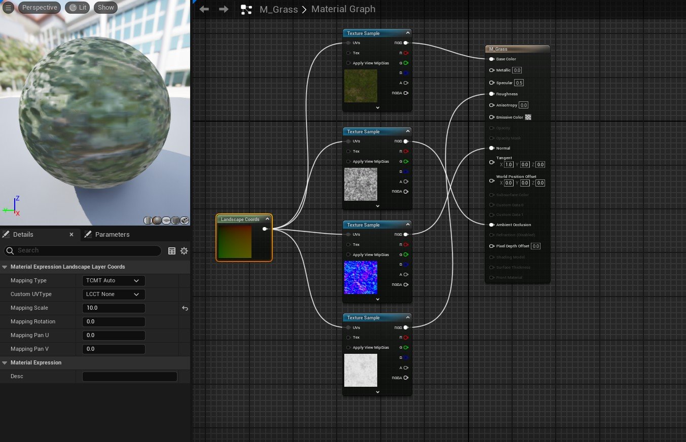
Figure 5.8
Once the terrain was properly sculpted, I could then add specific effects to make the hills look more realistic. This task was conducted using the erosion tool, which was a tool that I was not familiar with; however, this became very crucial for creating damaged and eroded areas in the hills. Alongside this, I utilised the flatten tool to create circular flat faces that could be eroded into the mountain; the smooth tool proved useful for making the hills more bumpy than sharp, which resulted in the hills feeling more realistic and appropriate for my scene.
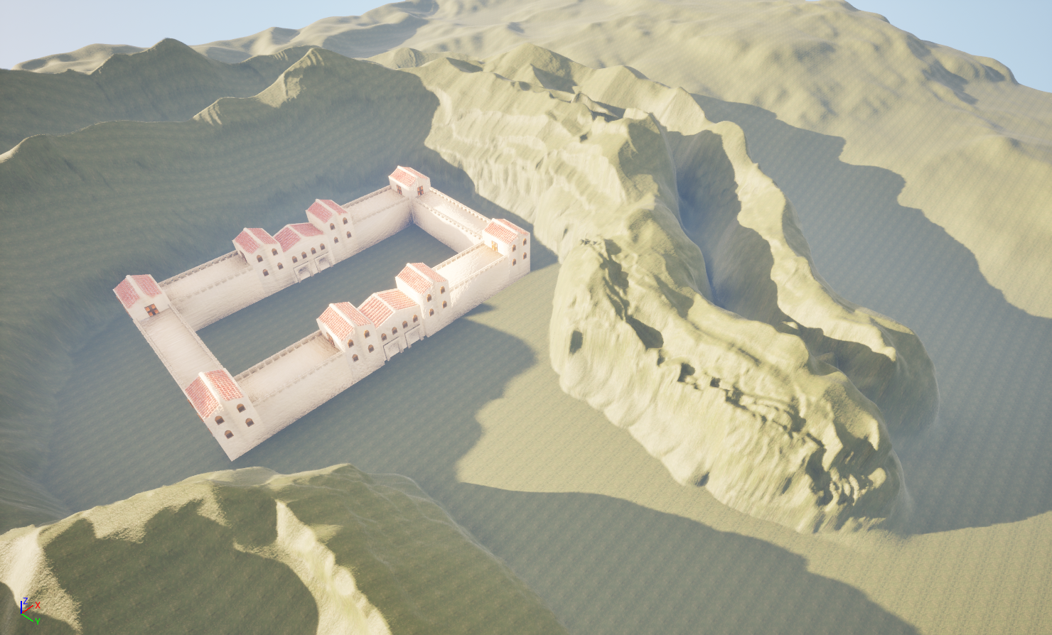
Figure 6
The construction of the landscape began by sculpting the terrain upwards to create hills that resembled a semi-circle shape that surrounds the scene enough, while also offering a clear and direct path for a player. To understand the scale of the scene, I decided to import the Roman fort into the scene, since this was the hero asset of the Diorama.
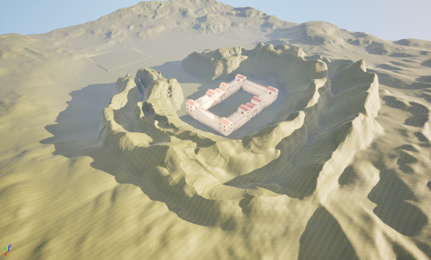
Figure 5.9
Environment Development Process
Stage 03: Asset Texture Maps
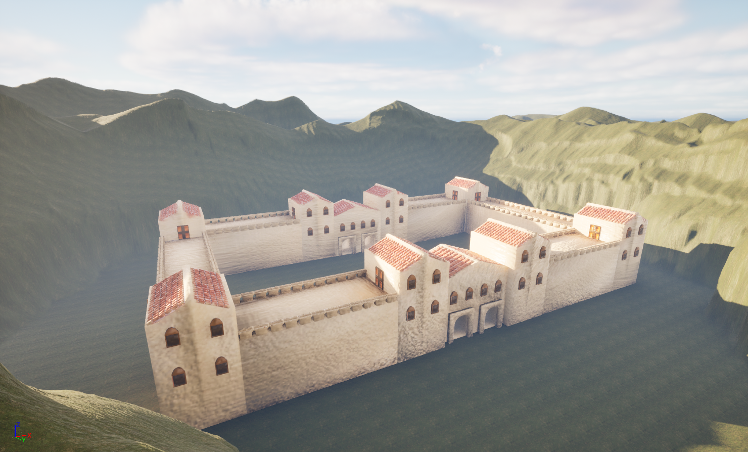
Figure 6.1 Figure 6.2
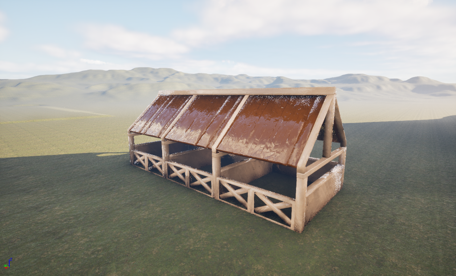
Figure 6.3 Figure 6.4
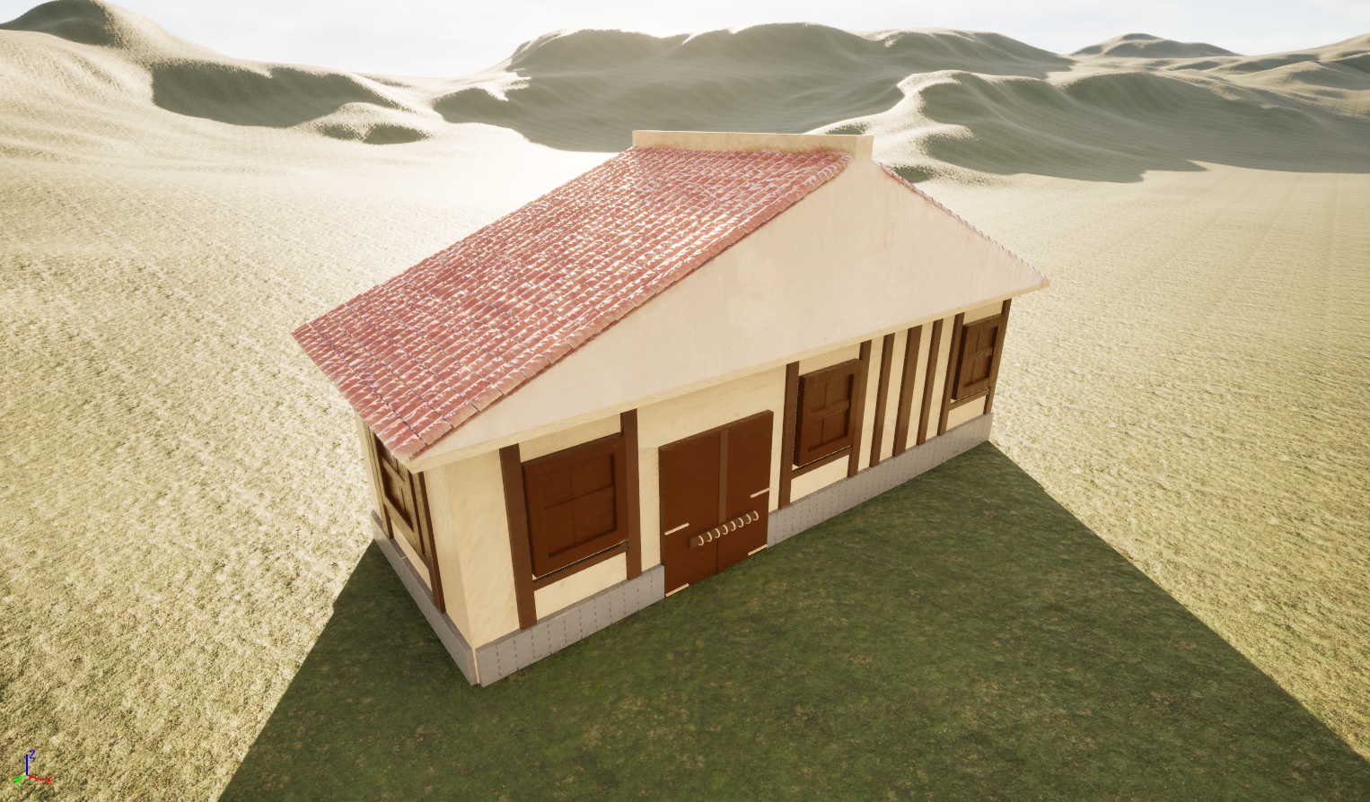
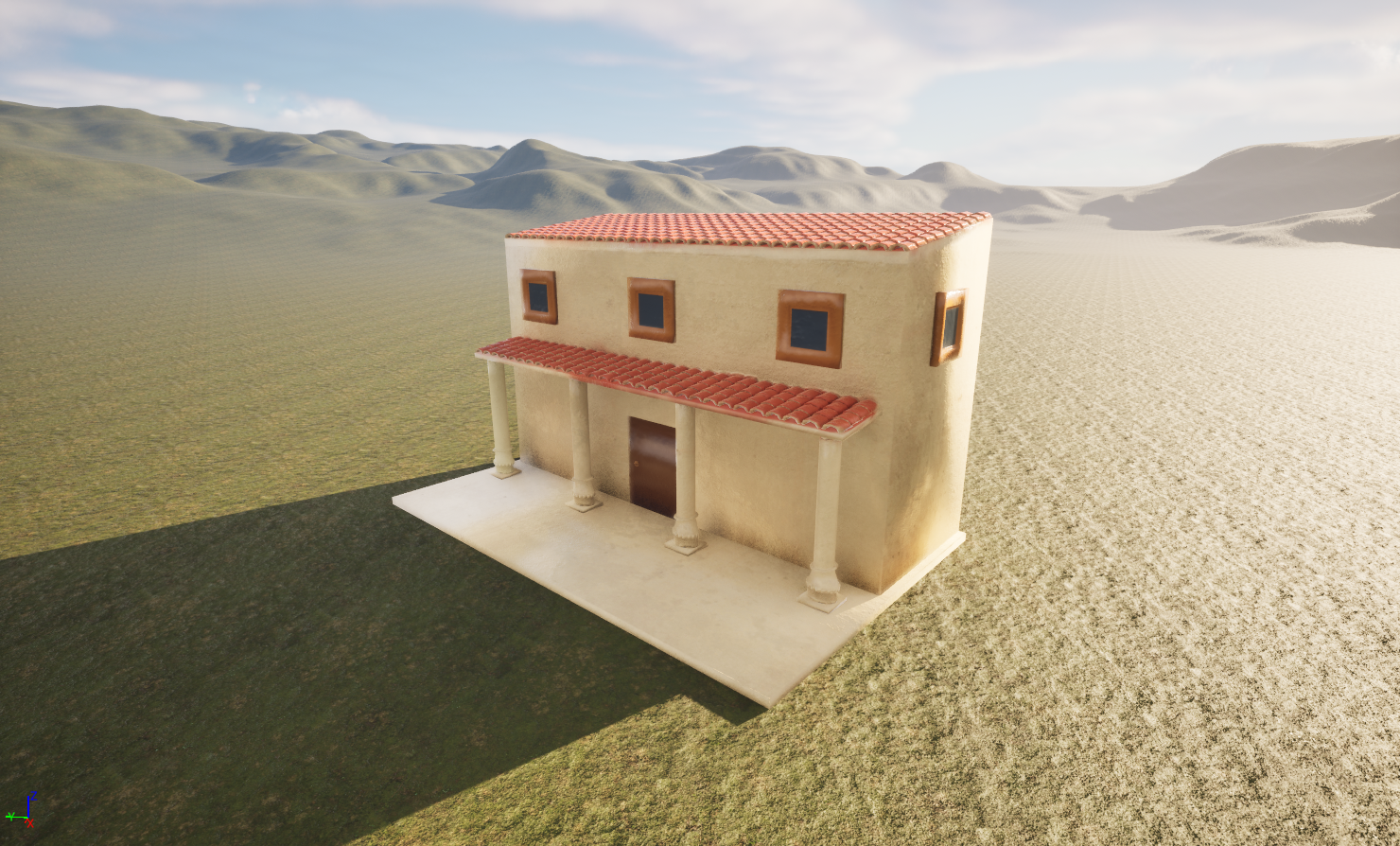
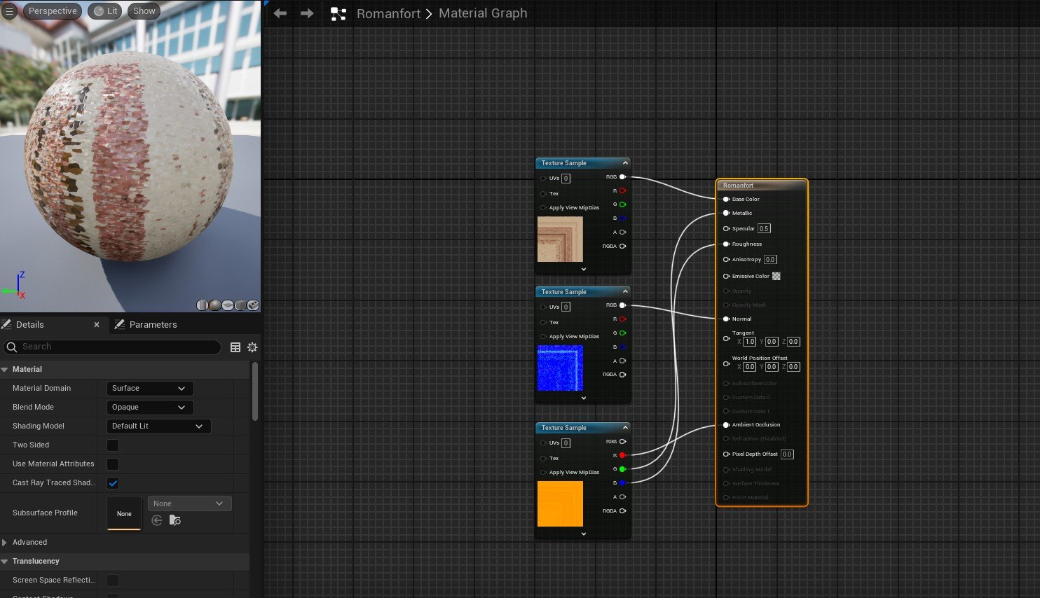
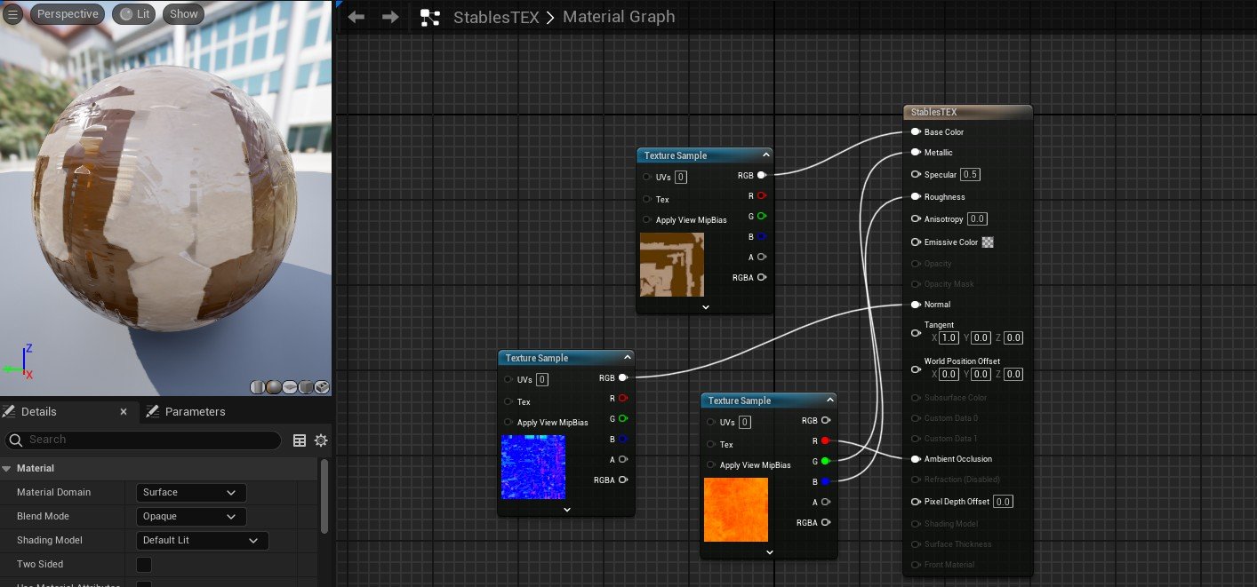
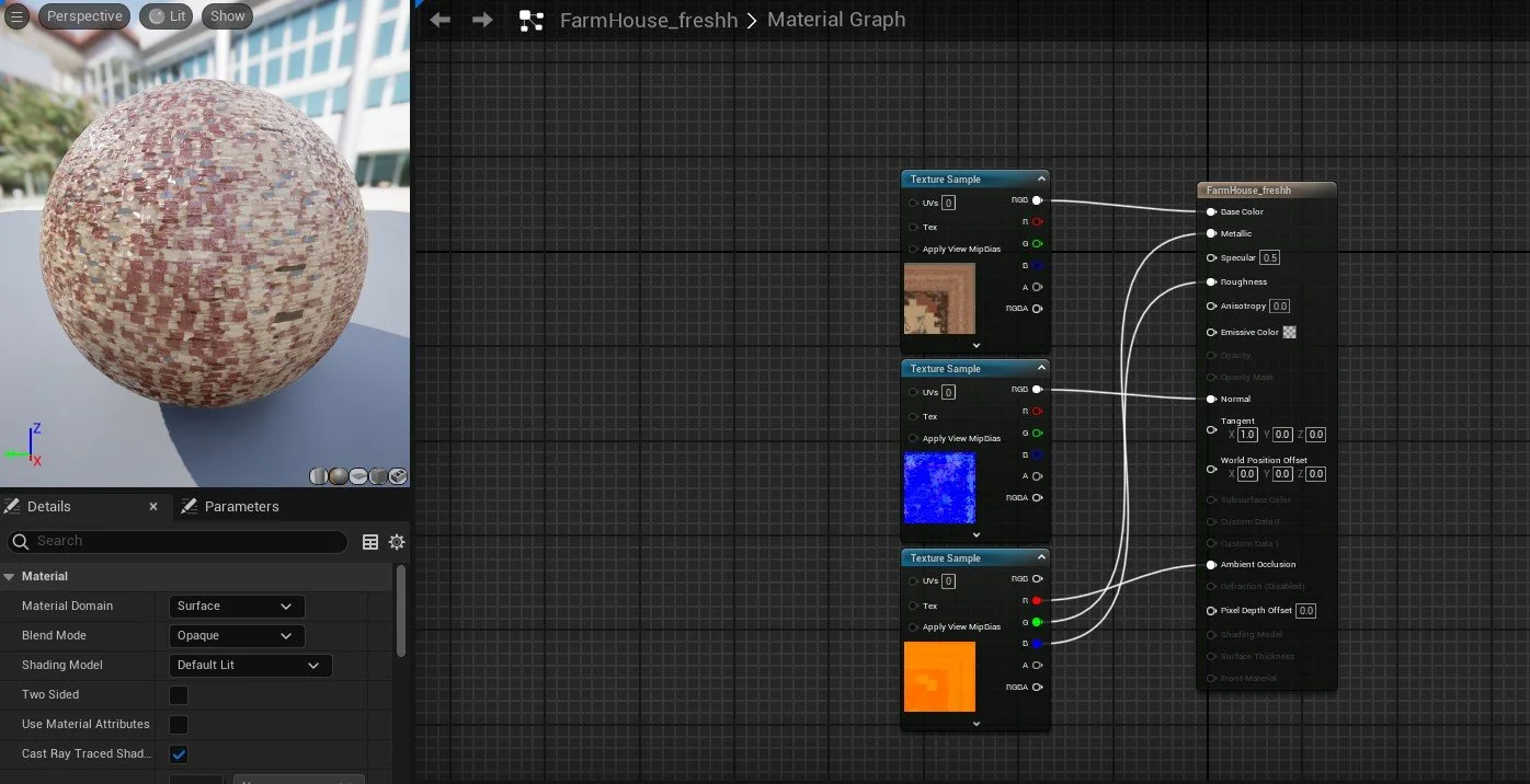
Figure 6.5 Figure 6.6
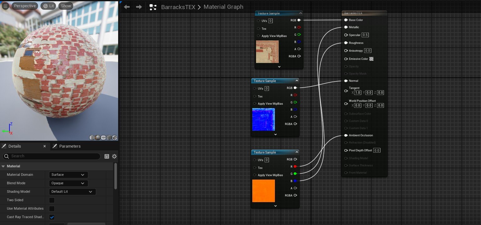
Figure 6.7 Figure 6.8
Environment Development Process
Stage 04: Fence development
During my development of the scene, I decided to 3d model a wooden fence that would be placed alongside the stone pathway. This was not originally planned; however, I felt this would enhance my project massively and give greater depth to the approach to the castle.
Due to time constraints and the project's lateness, I decided to go with a basic wooden design. The main skill used within this task was the bridge tool.
The tool was used to create the wooden beam between the two fence poles. This was done by adding a pair of swift loops to each pole, therefore allowing me to select specific faces and bridge them together.
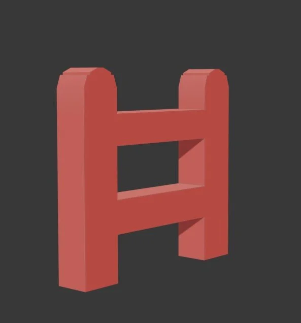
Figure 6.9
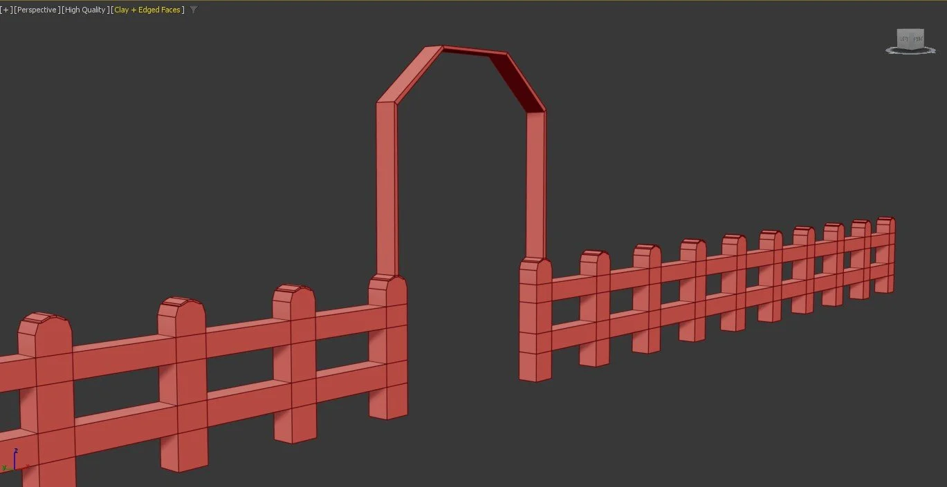
Figure 7
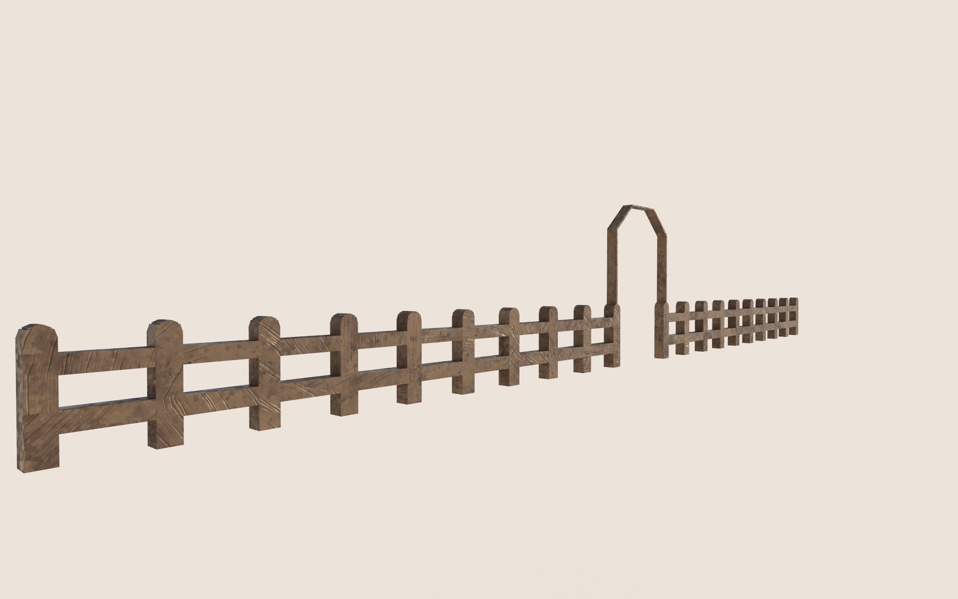
Fence Final Render (Substance Painter)
Fence Final Render (Unreal Engine 5)
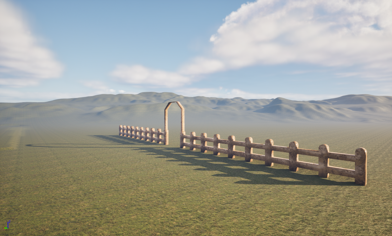
Figure 7.2
To create more visual detail, I decided to add an arched entrance that could direct players to other areas of the map. While this Diorama is not something that will be played, I feel this makes my environment look and feel more open for someone to explore.
To connect the archway together, I extruded both faces inward and utilised the bridge tool, which demonstrated the ability to maintain new skills and keep the model accurate.
Figure 7.1
Fence Texture Maps
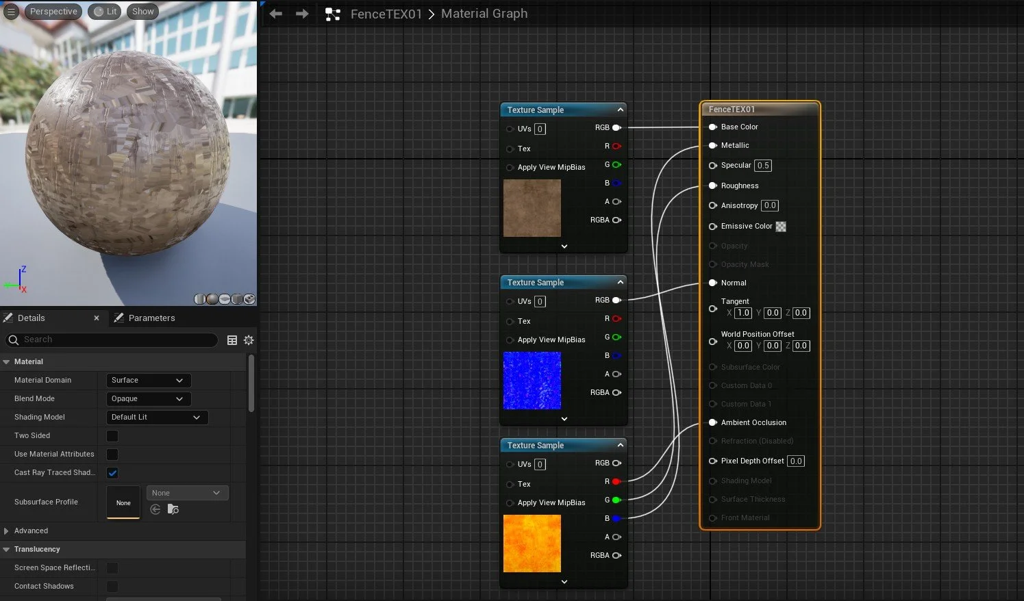
Figure 7.3
Environment Development Process
Scene Construction
Within this section, I will break down the process of creating the diorama and the development of the scene.
I decided to begin adding the pathway into the scene. Due to the straightness of the road, this process was very straightforward. To avoid scaling assets too much, I decided to duplicate both the fence and the pathway, which retained the texture quality and avoided the assets becoming too distorted. The straightness and engineering contribute to my project’s commitment to SDG 10; the controlled layout of the road demonstrates how movement within the Roman Empire was managed and organised. This reinforces the idea of authority and restricted access to military compounds. This specific point reflects on how my scene can represent systems of control and hierarchy.
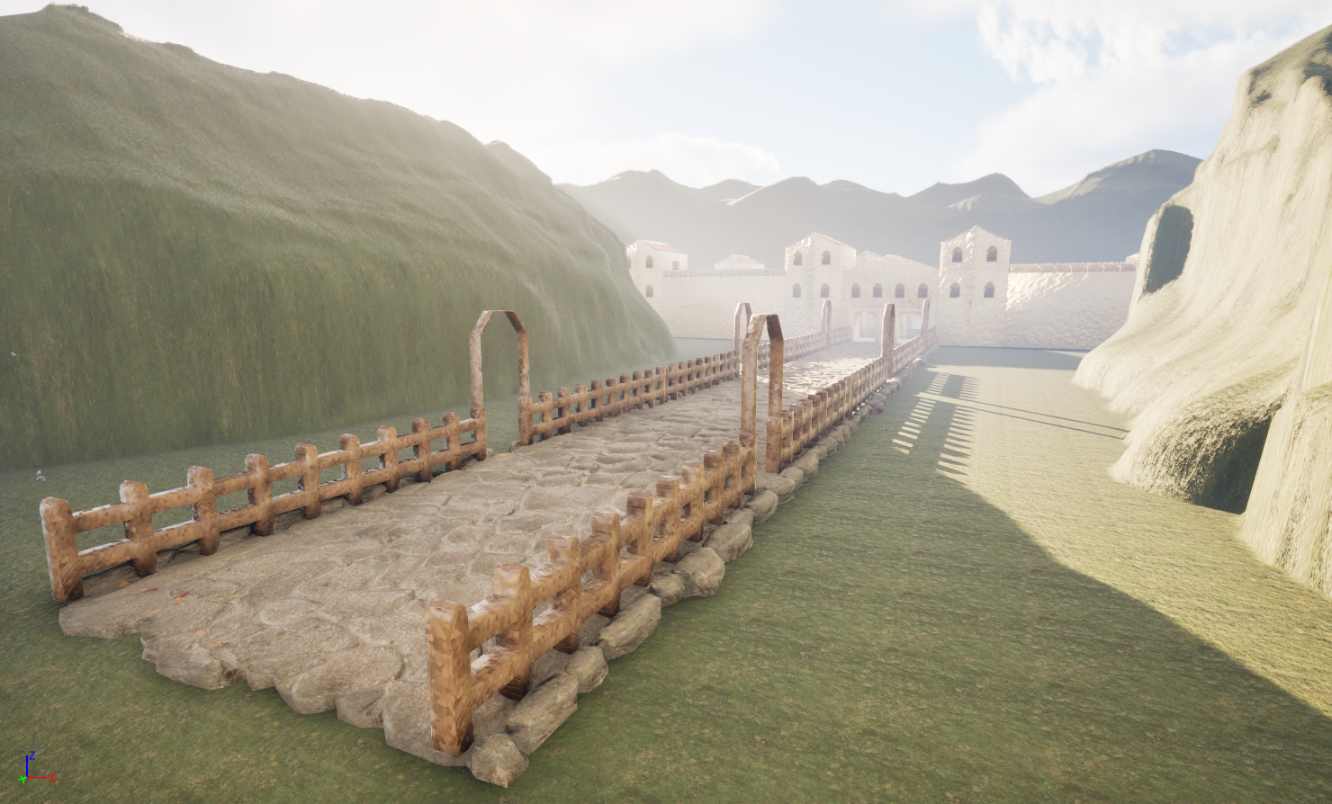
Figure 7.4
The Stables and the barracks were added to the scene and placed within the fort walls, while in Roman fort designs, I noticed that military and political buildings were kept within the fort. Both assets were cloned and kept in separate sections to demonstrate Roman origin and efficiency. This process links back to (History Rome, 2026). that discusses the importance that Romans placed on the organisation of military structures like the barracks.
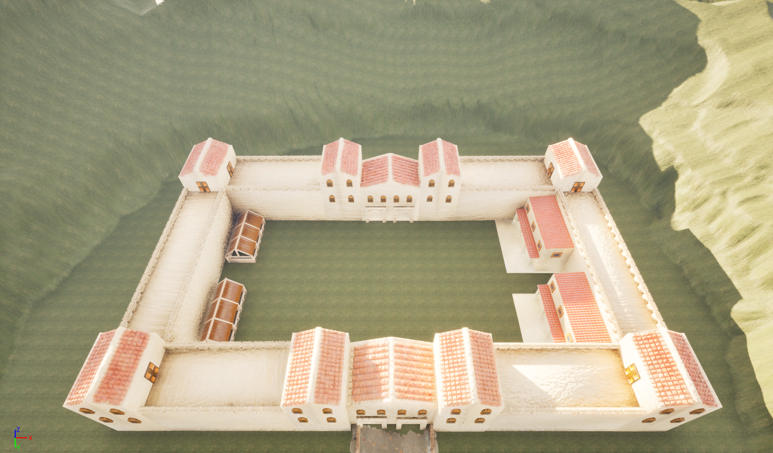
Figure 7.6
Figure 7.5
The first step of developing the foliage was to add the trees and grass into the scene that follows the pathway into the scene, and around the Roman fort. The purpose of this was to condense the scene and make it feel more compact and realistic for the scene. The new skill used for this task was the single instance asset tool, which offers quick duplication and controls the placement of the asset, which was effective for tighter spaces. The grass asset was added using the paint tool for quick placement and efficiency. The image situated within (Figure 7.9) outlines the tool and its settings.
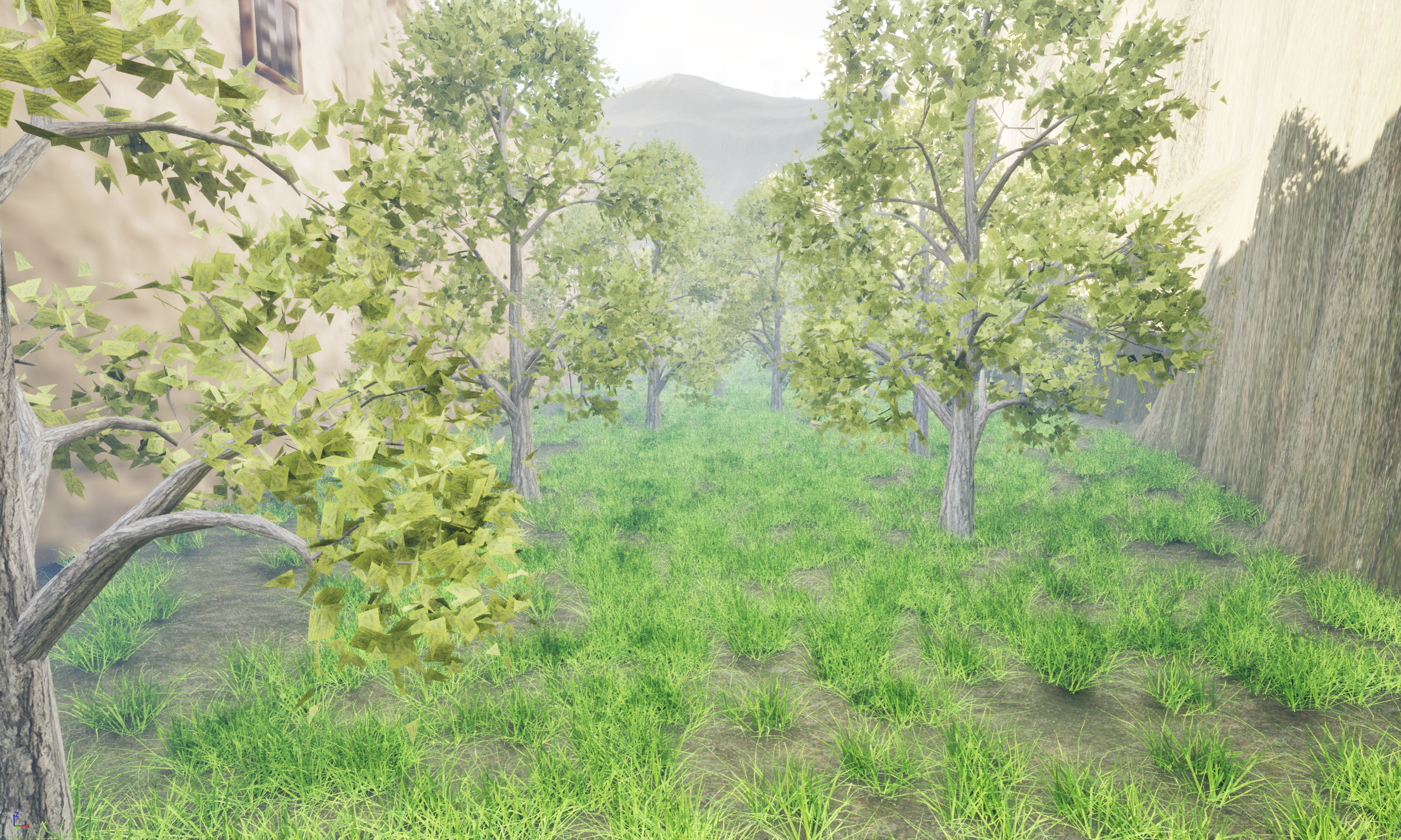
Figure 7.7
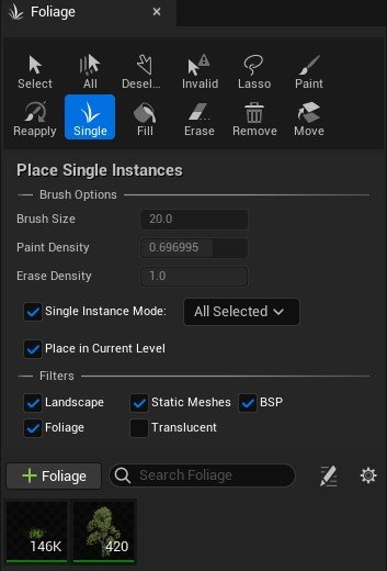
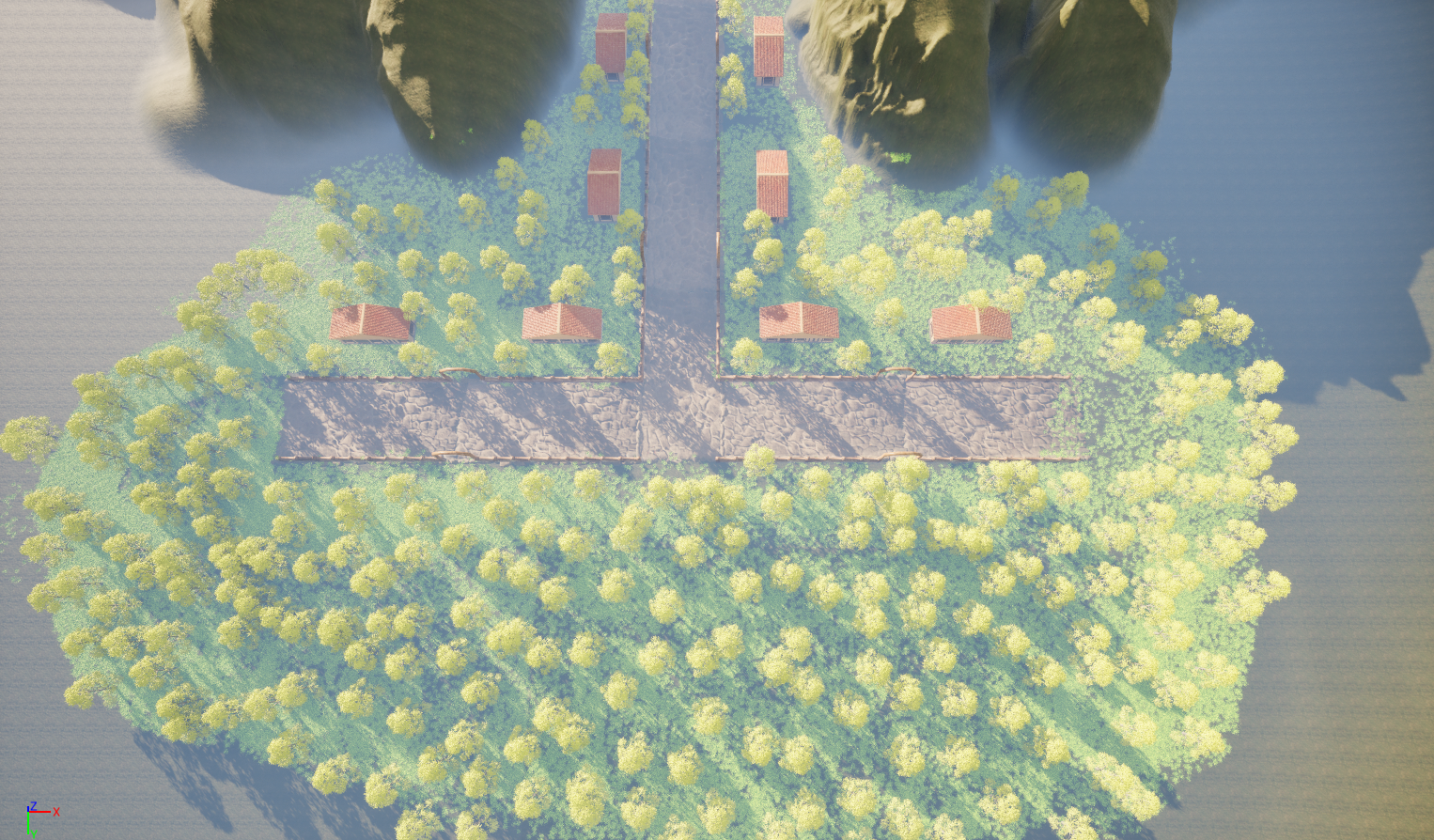
Figure 8
The biggest challenge with the farmhouse deployment was duplicating the assets. While the fence and pathway duplicated accurately, the farmhouse clones were smaller than the regular asset. This meant that I would have to manually scale the assets to ensure the consistency of the assets would be clear between the houses.
Foliage development 01
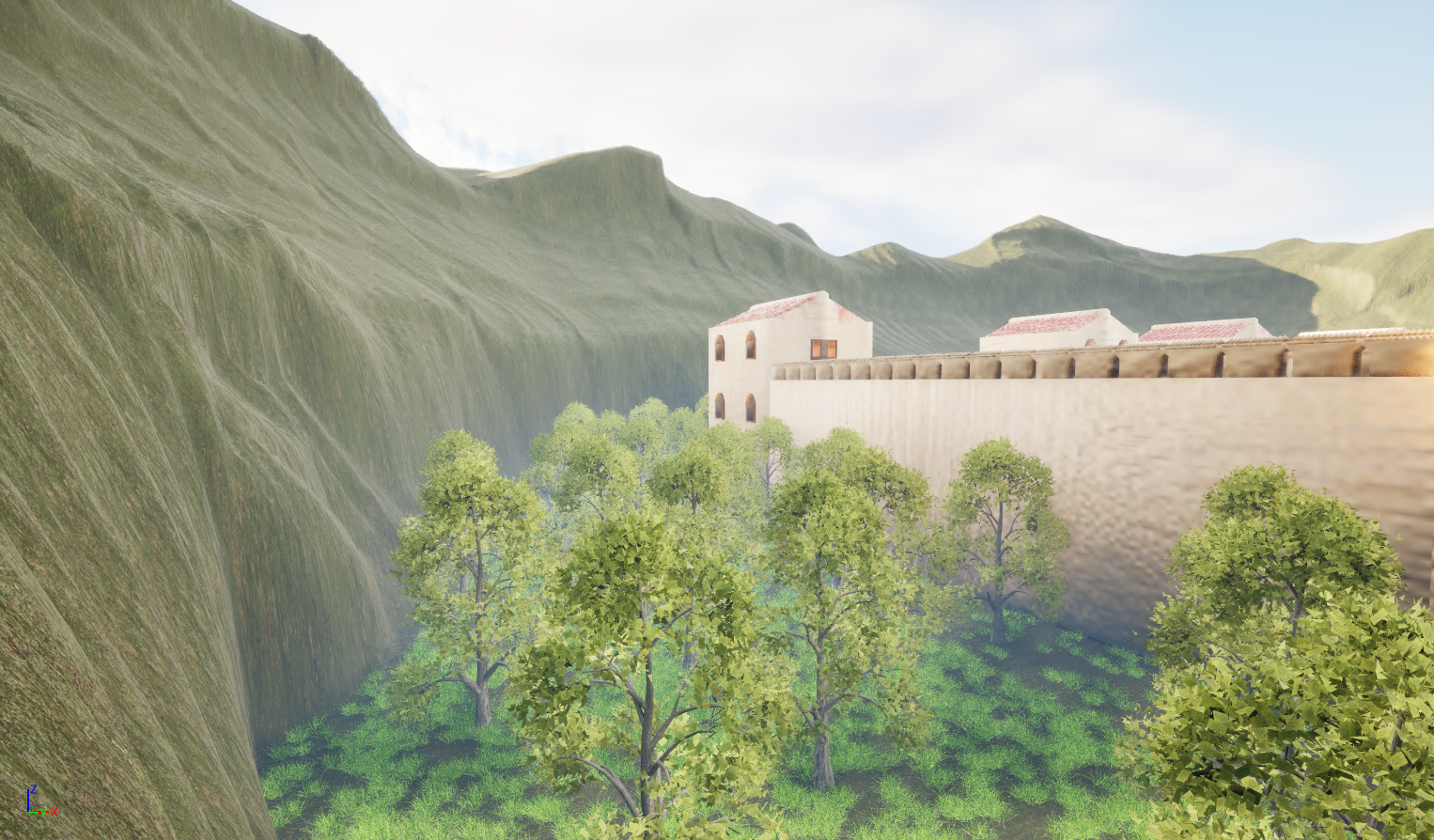
Figure 7.8
Figure 7.9
Foliage development 02 (Forest)
The final use of the foliage was to develop the forest that sets the starting point of the scene. The image contained within (Figure 8) demonstrates how the forest will be presented and its relationship with both the main scene and itself within a top-down view.
The second image within (Figure 8.1) shows my final work of the forest. The main method I used for this work was using the brush tool; due to the open space, I knew that I would need to place more trees at once. To control the amount placed, I reduced the density of the brush, which reduced the number of trees being placed. This resulted in the scene running slightly smoother and reduced strain on the PC, which in past projects has been a problem for me. The tool settings for the forest task can be located within (Figure 8.2)
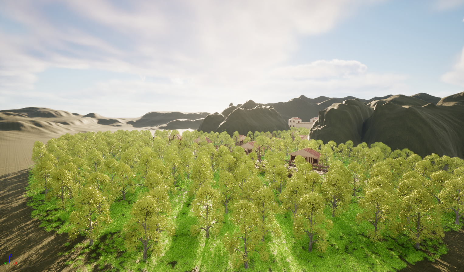
Figure 8.1
Figure 8.2
Fog Modifier
The final step for developing the environment was to add fog, which I feel will improve the feeling of the scene, but also will create a darker, more dreary atmosphere. The main challenge was creating lighting and fog that would be suitable for high-resolution screenshots. For this reason, depending on the image angle, I would adjust the modifier and change the settings (Figure 8.5.). Below are two screenshots that show how the scene looks before adding fog (Figure 8.3) and the aftermath of adding the fog (Figure 8.4).
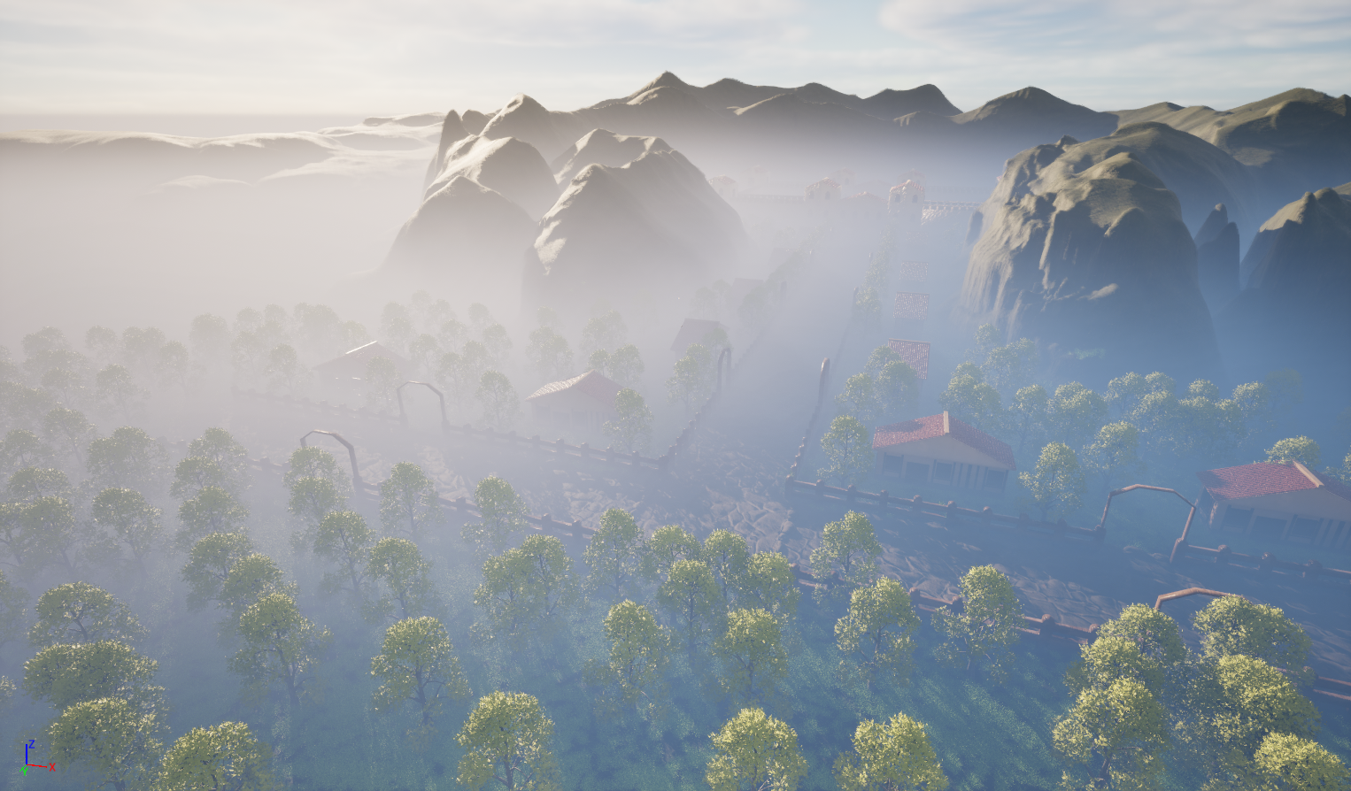
Figure 8.3 Figure 8.4
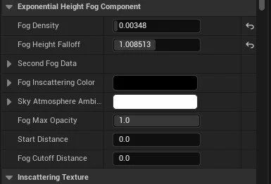
Figure 8.5
Roman Diorama (Final Renders)
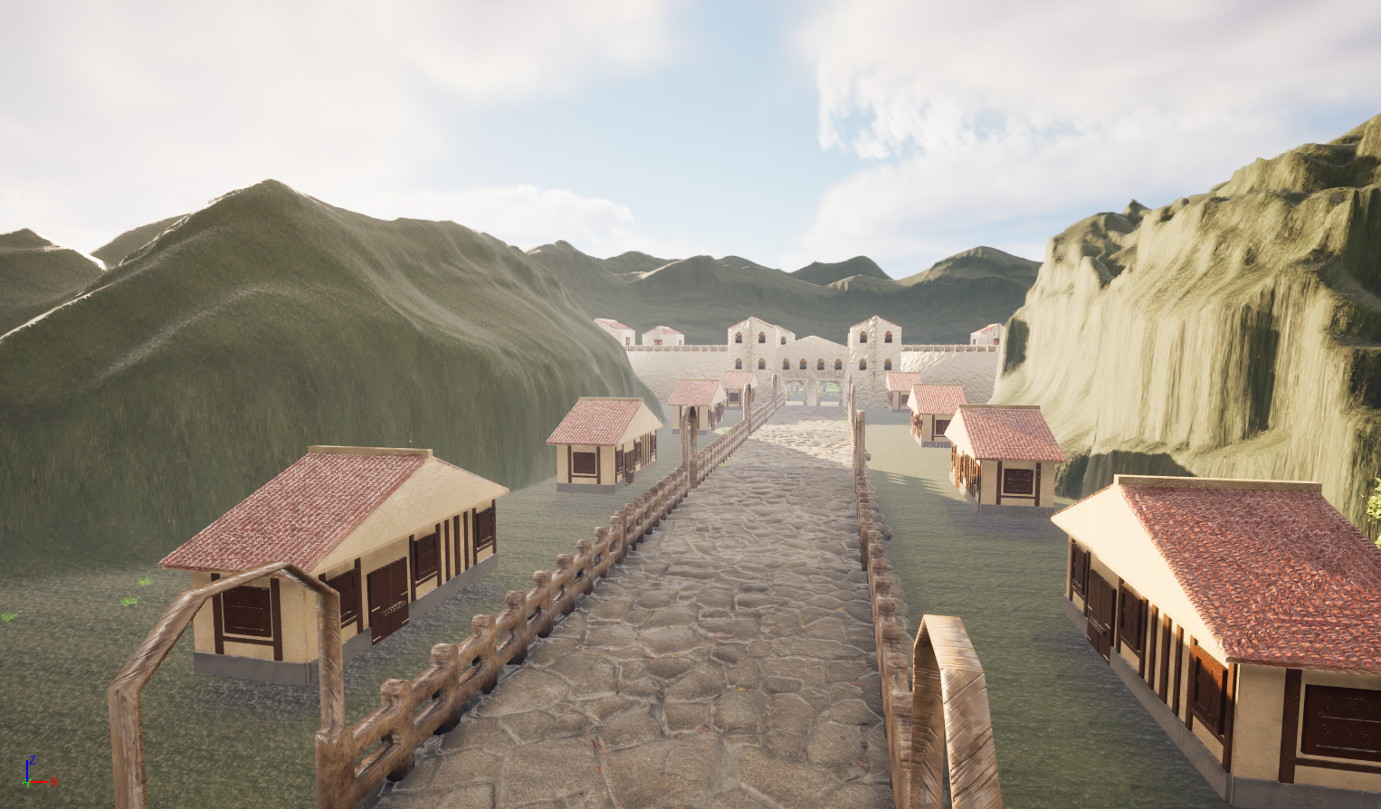
Roman Street View
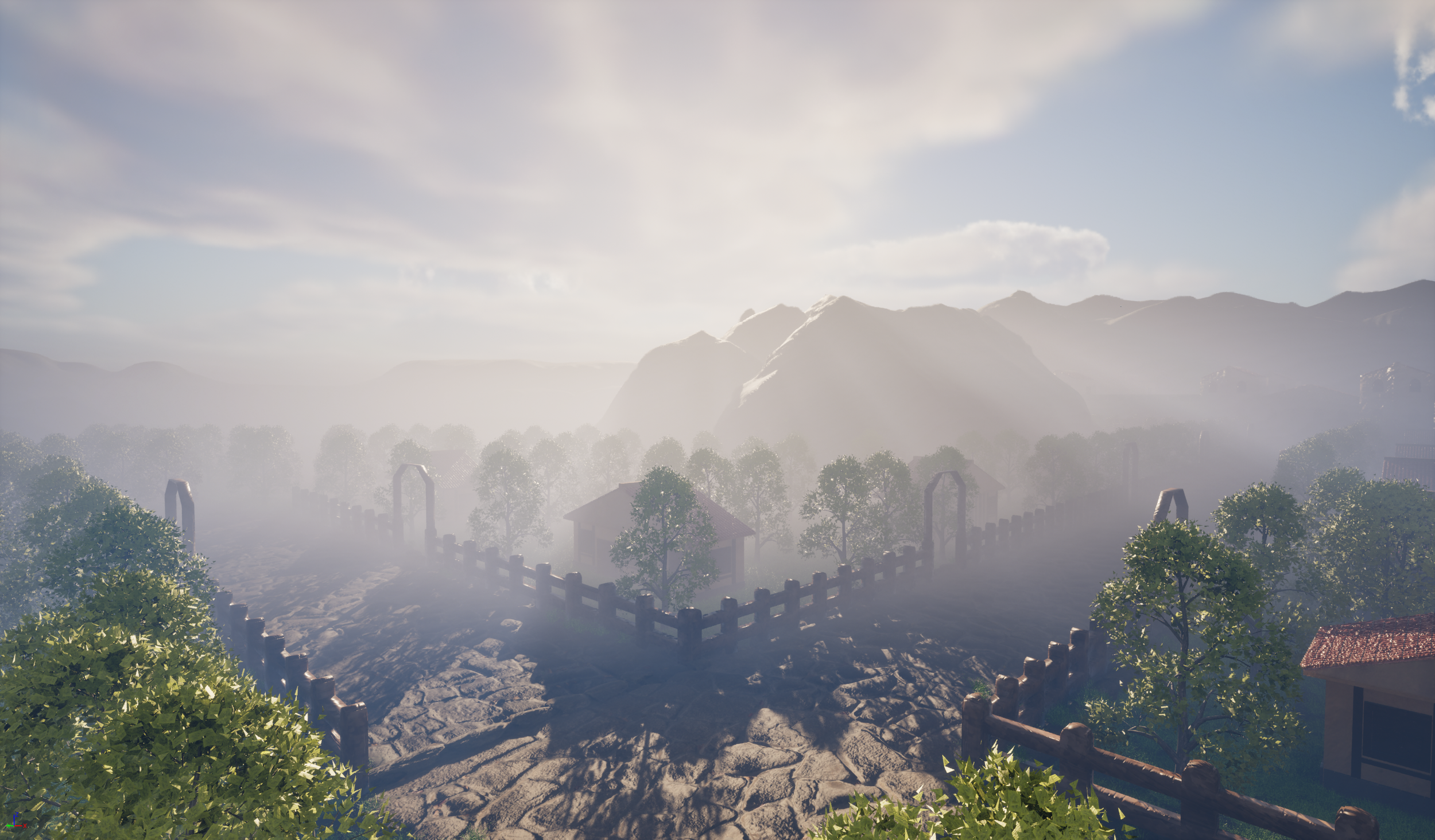
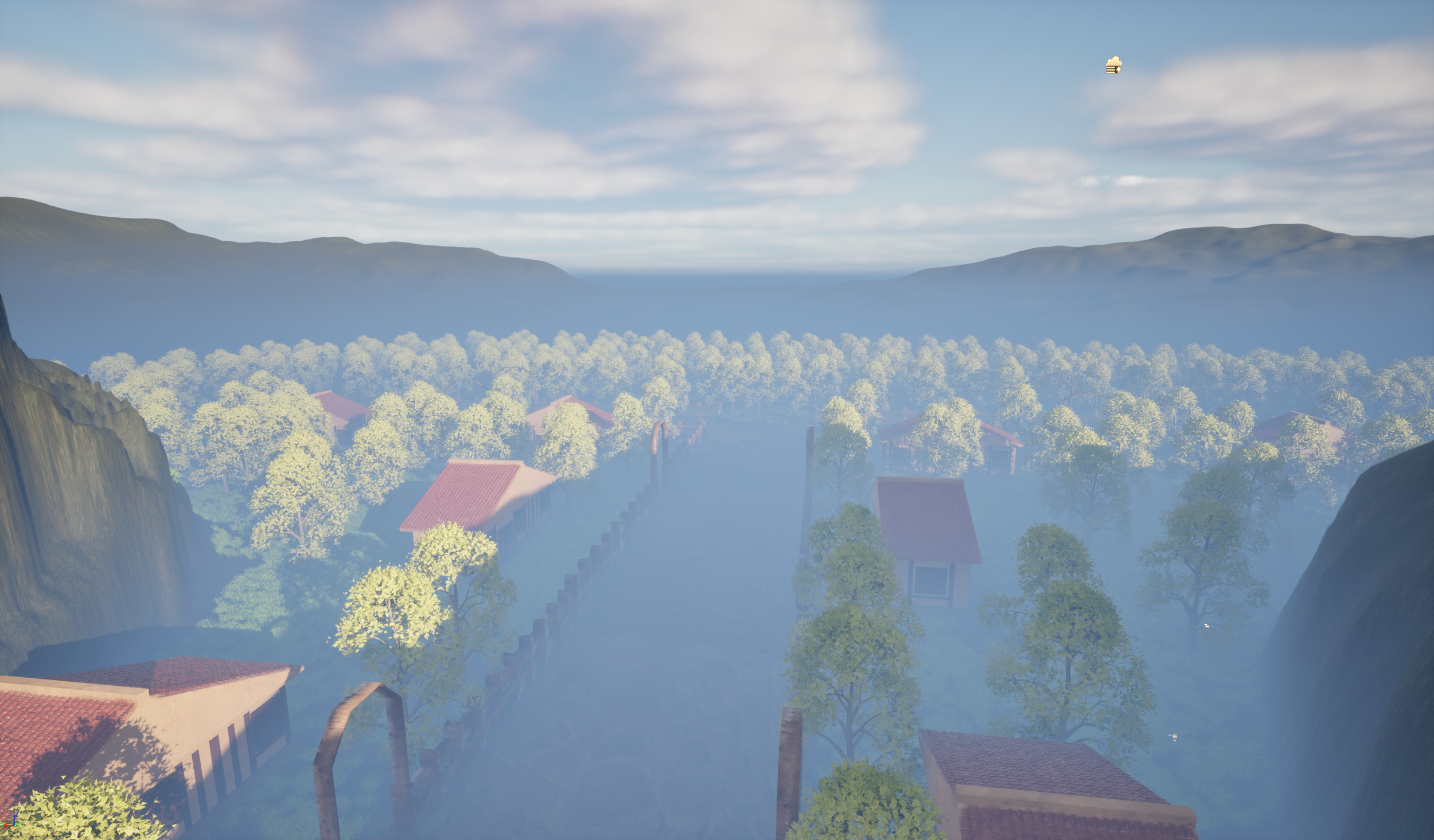
Figure 8.8
Forest Shots
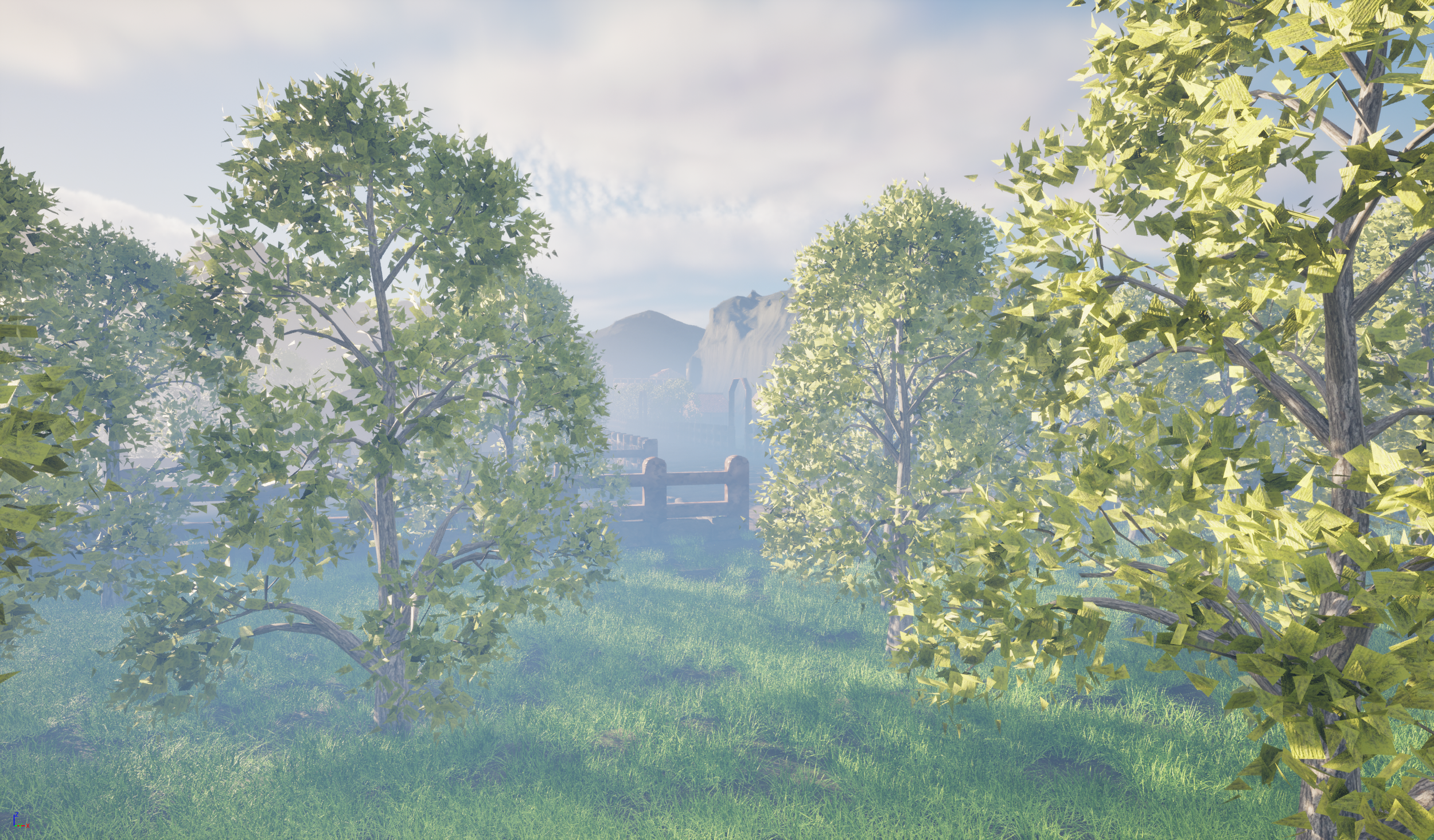
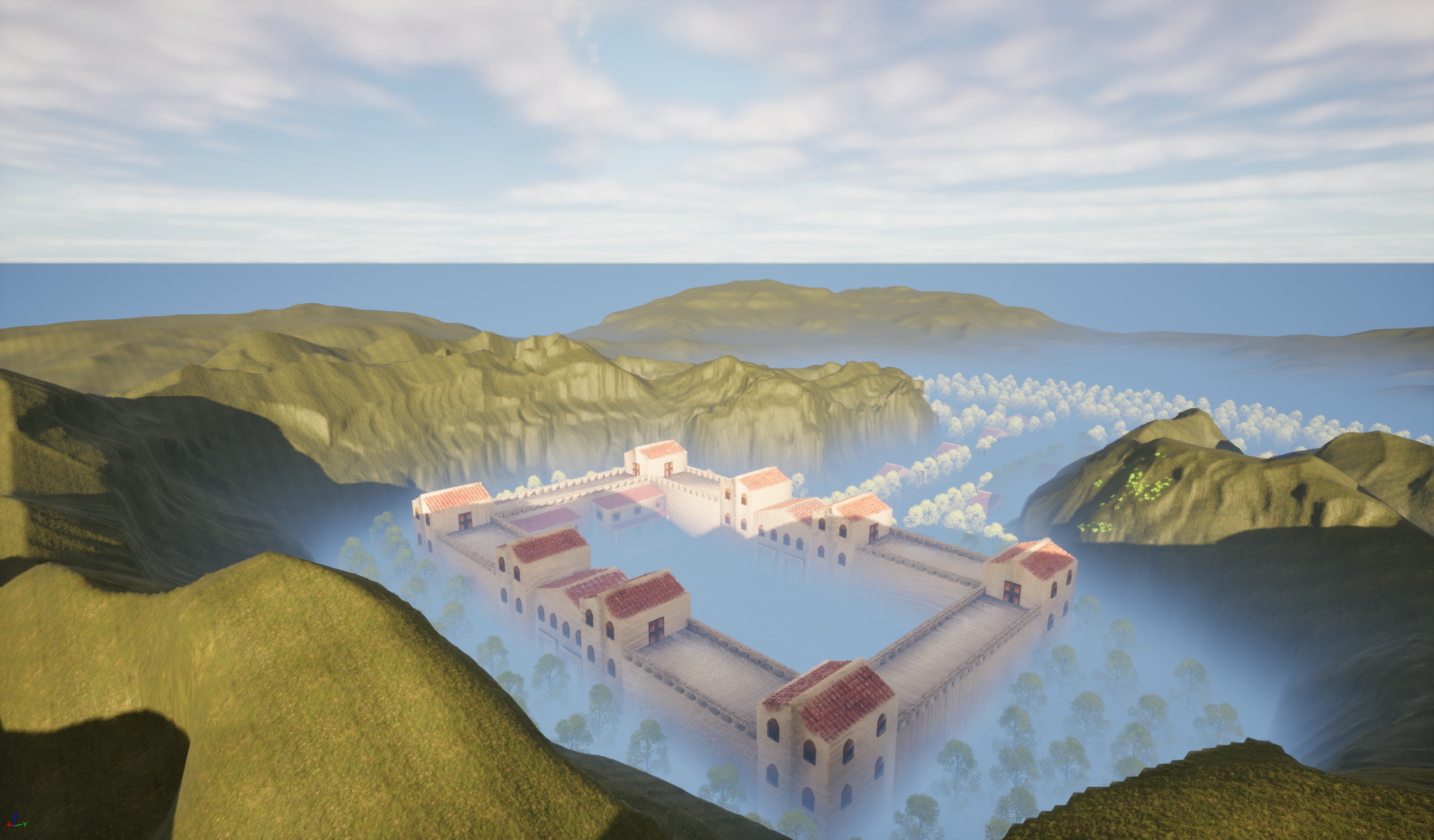
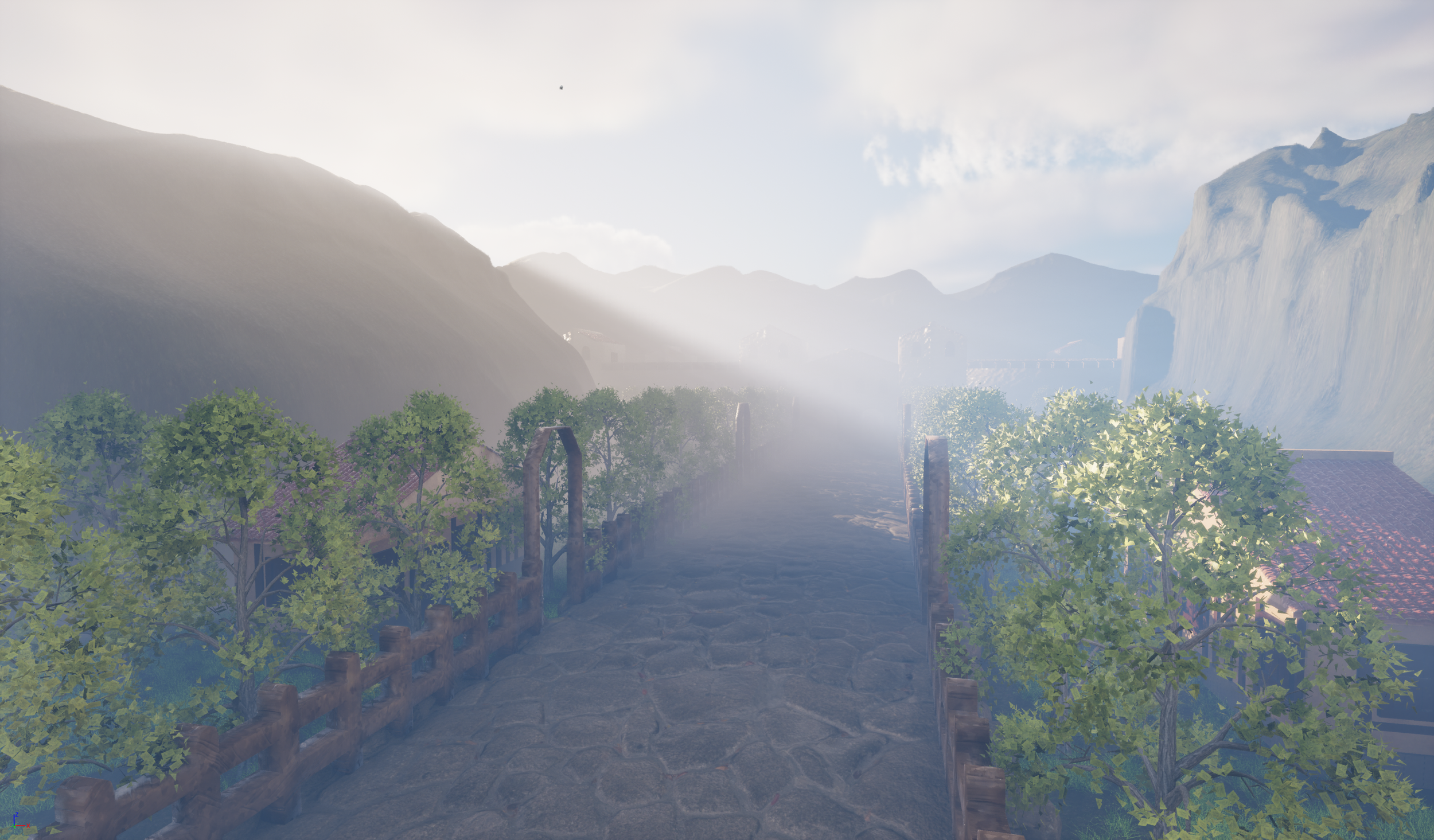
Figure 8.6 Figure 8.7
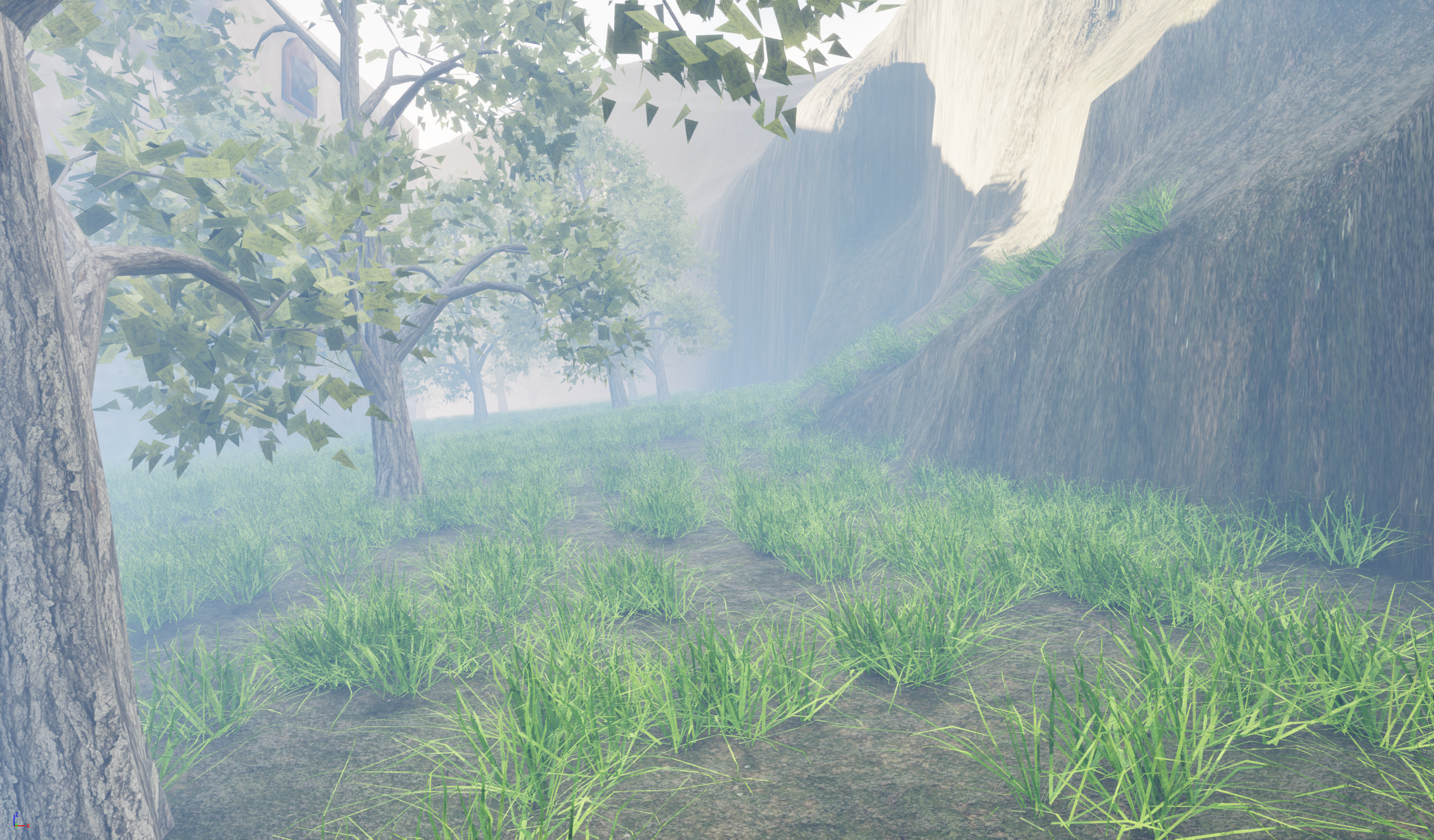
Figure 8.9 Figure 9
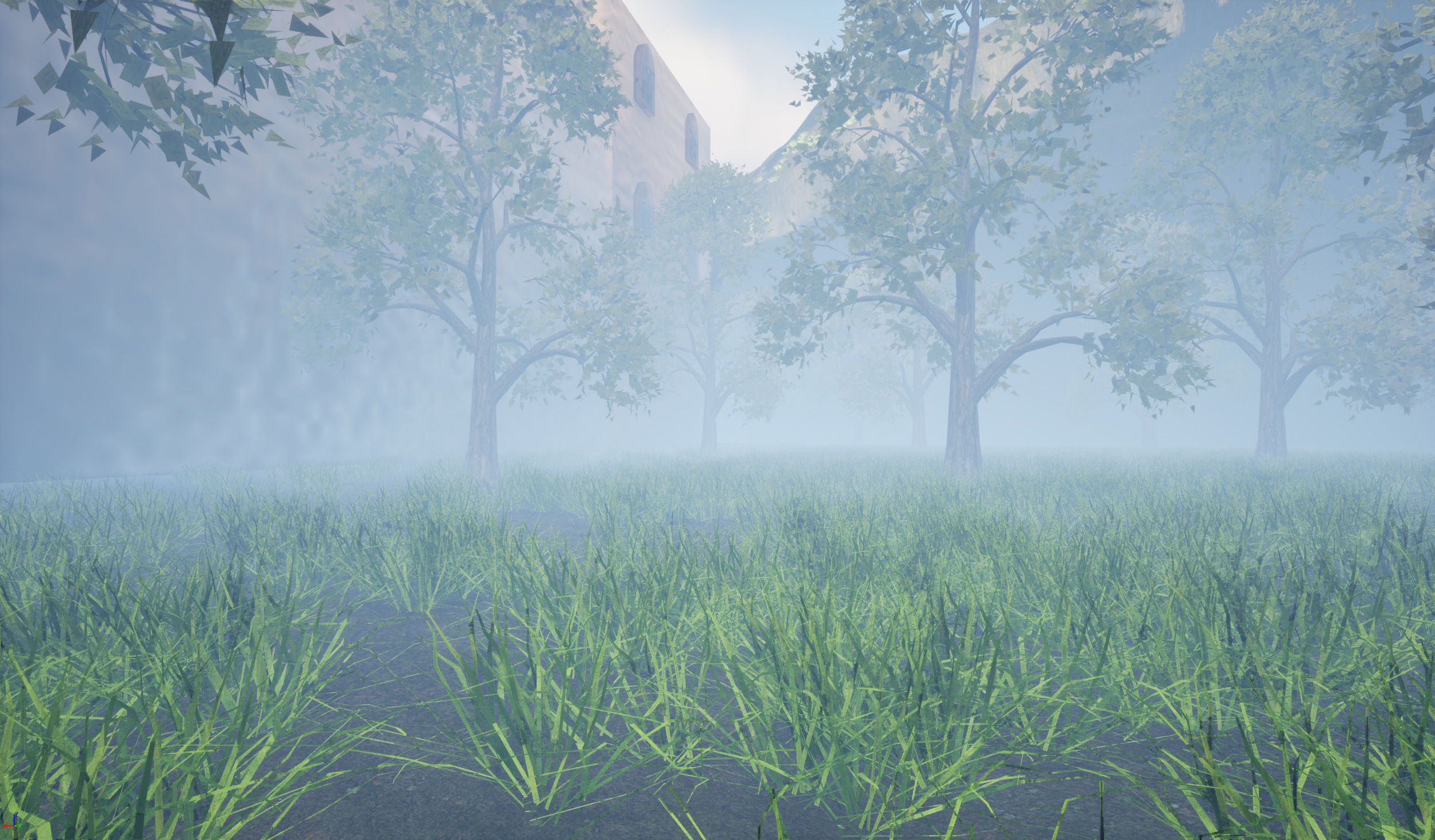
Figure 9.1
Vista Shots (Long range)
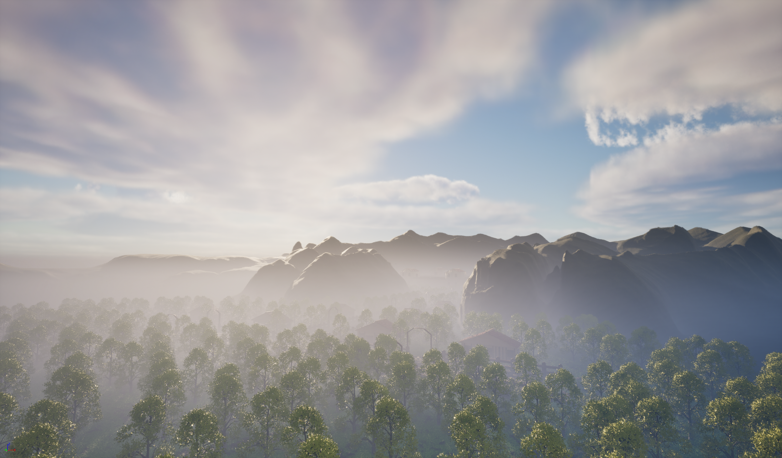
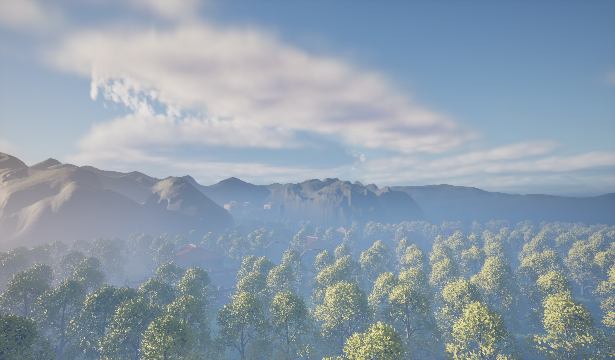
Figure 9.2 Figure 9.3
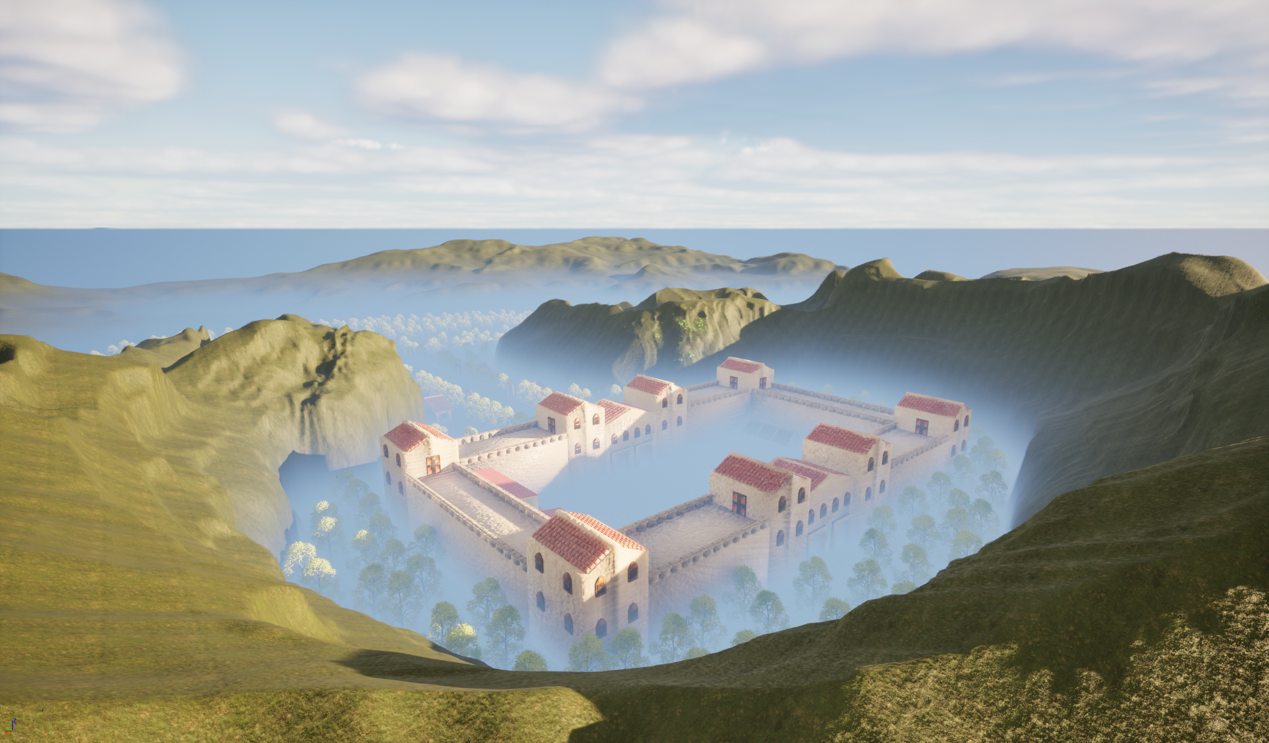
Figure 9.4 Figure 9.5
Fort Interior Shots
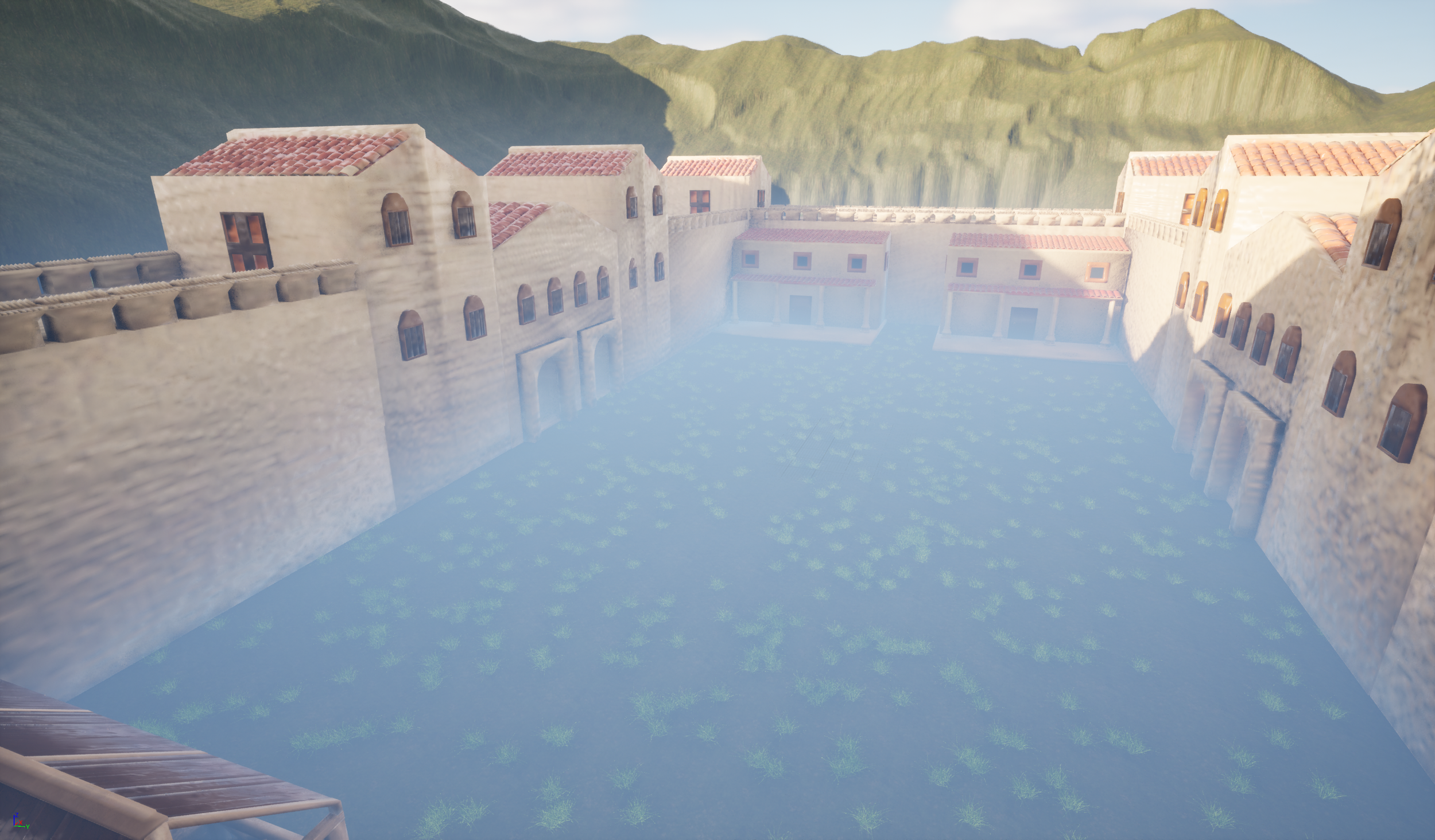
Figure 9.6 Figure 9.7
Conclusion
To begin concluding the project, I felt that it was ultimately a success. The hero asset and multiple secondary assets allowed me to demonstrate current and new skills that I was unaware of before this project. Skills like the construction of tiles for the fort, barracks, and farmhouse and the wooden planks for the stables, provided a visually appealing and historically accurate design that made my scene look more authentic and consistent. Challenges like the bricks placed along the (Figure 2.1) were difficult to manage due to the level of refinements that were required to ensure the model could be completed professionally and accurately.
The Environment design process involved using new skills for both the landscape and the deployment of foliage. New landscape skills like erosion and smoothing were crucial for creating realistic mountains and hills that could surround the scene and develop more depth for the scene. The foliage was a challenge due to the amount required and the heavy load on the pc. To manage this, the trees were placed using the single instance mode, which controlled density and the number of trees placed. This method ultimately lighten loaded and made it easier to complete that task.
The process of linking SDG 10 involved highlighting inequality, and the process was more difficult than I expected due to the Roman theme of my project. One way I addressed this was by adopting the hierarchical structure of the Roman Empire in a modern context. For example, during my sketch of the Roman barracks (Figure 1.4), I conducted research into the Roman barracks layout (History Rome, 2026), which informed my direction of my project, particularly through organised living spaces that reflect hierarchy and inequality. This allowed me to advance my critical thinking of the design process and therefore improve my clarity of the direction I could go with the development of the barracks. Other examples, like the fort sketch (Figure 1), focus on the heavy investments the Romans made into military forts at the expense of the welfare of the civilians. This demonstrated my awareness of the SDG goal and how it influenced my design process and wider thoughts on the ethical considerations within the project.
The project had multiple positives; the modelling development process involved a deeper reflection and greater critical analysis of the process, evidence of this was made during the process of the Roman fort. I made significant changes, which in the long term improved the fort and allowed me to demonstrate my approach to dealing with challenges. The use of UE5 proved to be complex but productive. While I had not used a game engine for many of my projects, I was able to develop new skills and techniques in order to create a unique Roman scene. The integration of SDG 10 had its challenges; however, I was able to overcome them by understanding the goals and integrating them into the development process.
If I were to undertake this project, I would focus on discussing the texturing process and adding a cinematic. I believe the cinematic would have offered opportunities for developing different perspectives and would have allowed me to further develop my skills. Discussing the texturing process would have demonstrated my skills; therefore, outlining the process from ideation, modelling, and finally texturing. To conclude, I am very satisfied with the outcome of the project, and I know that the work I have conducted has been incredibly productive and has overall strengthened the design process.
Handover files
My handover files contain the exported FBX 3d assets and their respective textures. The design documentation can be found below within Sketchfab.
Figure 9.8
Figure 9.9
SketchFab (Design documentation)
Figure 10
Figure 10.1
References
Exploring Building History (2022) ‘Villa Ventorum at The Newt – A Roman estate reimagined (Part 1): looking at the exterior’. Exploring Building History, 7 August. Available at: https://www.exploringbuildinghistory.co.uk/villa-ventorum-at-the-newt-a-roman-estate-reimagined-part-1-looking-at-the-exterior/
(Accessed: 4 December 2025).
HeritageDaily (2018) ‘10 Roman forts in Britannia’. Available at: https://www.heritagedaily.com/2018/01/10-roman-forts-britannia/117215
(Accessed: 4 December 2025).
Historic England (2018) Roman forts and fortresses. Swindon: Historic England. Available at: https://historicengland.org.uk/images-books/publications/iha-roman-forts-fortresses/heag230-roman-forts-fortresses/
(Accessed: 4 December 2025).
History Rome (2026) ‘Roman military forts: how they were built and why they were unbreakable’. Available at: https://history-rome.com/roman-military-forts-how-they-were-built-and-why-they-were-unbreakable/
(Accessed: 4 December 2025).
MyMiniFactory (2022) Roman barracks building – End of Empire. Available at: https://www.myminifactory.com/object/3d-print-roman-barracks-building-end-of-empire-215413
(Accessed: 4 December 2025).
Next Spring (2025) HighPoly Tree Model. Available at: https://www.fab.com/listings/2f1f43fe-fd59-42ff-967d-c8eb1a0785e7
(Accessed: 4 December 2025).
Ogussstavo (2025) Grass. Available at: https://www.fab.com/listings/2451d872-1c21-463e-ad43-2d237e9366ea
(Accessed: 4 December 2025).
Quixel Megascans (2024) Forest floor. Available at: https://www.fab.com/listings/dae56d09-862c-4f77-9e72-a41281c49633
(Accessed: 4 December 2025).
Quixel Megascans (2024) Japanese park stone floor. Available at: https://www.fab.com/listings/356c1a4c-94ef-48fe-8613-da4b5d48a60d
(Accessed: 4 December 2025).
The Archaeologist (2024) ‘The remarkable engineering of Roman roads: a legacy of durability and precision’. The Archaeologist, 5 November. Available at: https://www.thearchaeologist.org/blog/the-remarkable-engineering-of-roman-roads-a-legacy-of-durability-and-precision
(Accessed: 4 December 2025).
Bibliography
Epic Games (n.d.) Creating Landscapes in Unreal Engine. Available at: https://dev.epicgames.com/documentation/unreal-engine/creating-landscapes-in-unreal-engine?lang=en-US (Accessed: 4 December 2025).
JemGames (2025) How to create landscapes in Unreal Engine 5. YouTube. Available at: https://www.youtube.com/watch?v=8klqUw4pvSc (Accessed: 3 May 2026).
United Nations (n.d.) Goal 10: Reduced inequalities. The Global Goals. Available at: https://globalgoals.org/goals/10-reduced-inequalities/ (Accessed: 4 December 2025).
Why Tile (2024) Ancient Roman tile history and inspiration. Available at: https://whytile.com/tile-history/ancient-roman-tile-history-and-inspiration/ (Accessed: 3 May 2026).